INSTRUMENT CLUSTER INPUT/OUTPUT CHECK MODE
id092200801700
Check Code Table
Check code |
Check item |
Related items |
---|---|---|
08
|
TNS relay
|
• Lights-on reminder warning alarm
• Each illumination light
|
12
|
Speedometer
|
Speedometer
|
13
|
Tachometer
|
Tachometer
|
14
|
Buzzer
|
Buzzer
|
16
|
Fuel-level warning light
|
Fuel-level warning light
|
22
|
Fuel gauge sender unit
|
Fuel gauge
|
23
|
Fuel gauge
|
Fuel gauge
|
25
|
Water temperature gauge
|
Water temperature gauge
|
26
|
• Odometer/tripmeter (LCD)
• Warning and indicator light
|
• Odometer/tripmeter (LCD)
• Warning and indicator light
|
31
|
Key reminder switch
|
Key reminder warning alarm
|
32
|
Indicator buzzer
|
Indicator buzzer
|
55
|
Dimmer switch
|
—
|
62*
|
• CAN system
• Cruise control switch
|
• CAN system
• Cruise control system
|
63
|
Passenger seat belt reminder indicator
|
Seat belt warning system
|
am3zzw00001963
|
Checking Order
Priority order of inspection |
Ignition switch position |
Check code |
---|---|---|
1
|
ON
|
22
|
2
|
08, 12, 13, 14, 16, 23, 25, 26, 55, 62, 63
|
|
3
|
LOCK
|
31, 32
|
Check Code Inspection
Check code 08
Check code 08 |
TNS relay ON/OFF signal |
|||
---|---|---|---|---|
STEP |
INSPECTION CONDITION |
DISPLAY |
ACTION |
|
1
|
Turn the headlight switch to the TNS position. (TNS relay ON)
|
![]() |
Go to the next step.
|
|
![]() |
Verify that the voltage of instrument cluster terminal 1L is B+.
• If the voltage is as specified, replace the instrument cluster.
• If the voltage is not as specified, inspect the following parts:
|
|||
2
|
Turn the headlight switch off. (TNS relay OFF)
|
![]() |
Verify that the voltage of the instrument cluster terminal 1L is 1.0 V or less.
• If the voltage is as specified, replace the instrument cluster.
• If the voltage is not as specified, inspect the following parts:
|
|
![]() |
Input signal to the instrument cluster is normal.
|
Check code 12
Check code 12 |
Speedometer display signal |
||||
---|---|---|---|---|---|
INSPECTION CONDITION |
DISPLAY |
ACTION |
|||
After selecting check code 12, wait for approx. 2 s.
|
![]() |
The speedometer needle moves full scale then returns to approx. 60 km/h.
|
The speedometer is normal.
|
||
Except above
|
Replace the instrument cluster.
|
||||
![]() |
—
|
Check code 13
Check code 13 |
Tachometer operation signal |
|||
---|---|---|---|---|
INSPECTION CONDITION |
DISPLAY |
ACTION |
||
After selecting check code 13, wait for approx. 2 s.
|
![]() |
The tachometer needle moves full scale then returns to approx. 3,000 rpm.
|
The tachometer is normal.
|
|
Except above
|
Replace the instrument cluster.
|
|||
![]() |
—
|
Check code 14
Check code 14 |
Buzzer operation signal |
|||
---|---|---|---|---|
INSPECTION CONDITION |
DISPLAY |
ACTION |
||
After selecting check code 14, wait approx. 2 s.
|
![]() |
The buzzer sounds.
|
The buzzer is normal.
|
|
The buzzer does not sound.
|
Replace the instrument cluster.
|
Check code 16
Check code 16 |
Fuel-level warning light flashing signal |
|||
---|---|---|---|---|
INSPECTION CONDITION |
DISPLAY |
ACTION |
||
After selecting check code 16, wait approx. 2 s.
|
![]() |
Fuel-level warning light flashes three times.
|
The fuel-level warning light is normal.
|
|
Except above
|
Replace the instrument cluster.
|
Check code 22
Check code 22 |
Fuel level signal |
|||
---|---|---|---|---|
STEP |
INSPECTION CONDITION |
DISPLAY |
ACTION |
|
1
|
Select check code 22 with the fuel gauge sender unit connector disconnected.
|
![]() |
Go to the next step.
|
|
Except above
|
Replace the instrument cluster.
|
|||
2
|
Connect terminals 2U and 2W of the instrument cluster.
|
![]() |
Go to the next step.
|
|
Except above
|
Replace the instrument cluster.
|
|||
3
|
Using the SST (Fuel and thermometer checker) or resistor, input 20 ohms between instrument cluster terminals 2U and 2W.
|
![]() |
Go to the next step.
|
|
Except above
|
Replace the instrument cluster.
|
|||
4
|
Using the SST (Fuel and thermometer checker) or resistor, input 100 ohms between instrument cluster terminals 2U and 2W.
|
![]() |
Go to the next step.
|
|
Except above
|
Replace the instrument cluster.
|
|||
5
|
Using the SST (Fuel and thermometer checker) or resistor, input 200 ohms between instrument cluster terminals 2U and 2W.
|
![]() |
Inspect the fuel gauge sender unit.
|
|
Except above
|
Replace the instrument cluster.
|
Check code 23
Check code 23 |
Fuel gauge operation signal |
|||
---|---|---|---|---|
INSPECTION CONDITION |
DISPLAY |
ACTION |
||
After selecting check code 23, wait approx. 2 s.
|
![]() |
The fuel gauge indicates status in the following order approx. every 2 s.
• F → 1/2 → E → F (fixed)
|
The fuel gauge is normal.
|
|
Except above
|
Replace the instrument cluster.
|
|||
![]() |
Replace the instrument cluster.
|
Check code 25
Check code 25 |
Water temperature gauge operation signal |
|||
---|---|---|---|---|
INSPECTION CONDITION |
DISPLAY |
ACTION |
||
After selecting check code 25, wait approx. 2 s.
|
![]() |
The water temperature gauge indicates status in the following order approx. every 2 s.
• H → Center → C → H (fixed)
|
The water temperature gauge is normal.
|
|
Except above
|
Replace the instrument cluster.
|
|||
![]() |
Replace the instrument cluster.
|
Check code 26
Check code 26 |
Odometer/tripmeter display signal |
|||
---|---|---|---|---|
INSPECTION CONDITION |
DISPLAY |
ACTION |
||
Select check code 26.
|
![]() |
• Display is normal.
• Warning and indicator light illuminated.
|
• The odometer/tripmeter is normal.
• Warning and indicator is normal.
|
|
Except above
|
Replace the instrument cluster.
|
Check code 31
Check code 31 |
Key reminder switch ON/OFF signal |
|||
---|---|---|---|---|
STEP |
INSPECTION CONDITION |
DISPLAY |
ACTION |
|
1
|
Turn the headlight switch to the TNS position.
Remove the key from the steering lock, then reinsert the key into the steering lock after selecting check code 31. (The key reminder switch is on.)
|
![]() |
Go to the next step.
|
|
![]() |
Verify that the voltage of instrument cluster terminal 2C is B+.
• If the voltage is as specified, replace the instrument cluster.
• If the voltage is not as specified, inspect the following parts:
|
|||
2
|
Remove the key from the steering lock. (The key reminder switch is off.)
|
![]() |
Verify that the voltage of instrument cluster terminal 2C is 1.0 V or less.
• If the voltage is as specified, replace the instrument cluster.
• If the voltage is not as specified, inspect the following parts:
|
|
![]() |
Input signal to the instrument cluster is normal.
|
Check code 32
Check code 32 |
Indicator buzzer |
|||
---|---|---|---|---|
INSPECTION CONDITION |
DISPLAY |
ACTION |
||
Turn the headlight switch to the TNS position.
After selecting check code 32, wait approx. 2 s.
|
![]() |
Indicator buzzer sounds three times.
|
The buzzer is normal.
|
|
The buzzer does not sound.
|
Replace the instrument cluster.
|
Check code 55
Check code 55 |
Dimmer switch ON/OFF signal |
|||
---|---|---|---|---|
STEP |
INSPECTION CONDITION |
DISPLAY |
ACTION |
|
1
|
After selecting the check code 55, press and hold the dimmer switch. (Dimmer switch ON)
|
![]() |
Go to the next step.
|
|
![]() |
Replace the instrument cluster.
|
|||
2
|
Release the dimmer switch. (Dimmer switch OFF)
|
![]() |
Replace the instrument cluster.
|
|
![]() |
Input signal to the instrument cluster is normal.
|
Check code 62
Diagnostic procedure
Check code 62 |
CAN system/cruise control switch signal |
|||
---|---|---|---|---|
STEP |
INSPECTION |
INDICATION |
ACTION |
|
1
|
The three digits number is indicated after selecting check code 59. Confirm the first digit from the right.
|
![]() |
The CAN system is okay.
Go to the next step.
|
|
![]() |
The DTC of CAN system is detected.
Perform the DTC inspection. (See DTC TABLE [MULTIPLEX COMMUNICATION SYSTEM])
• If the CAN system is okay, replace the instrument cluster.
Go to the next step.
|
|||
2
|
Confirm the second digit from the right.
|
![]() |
The wiring harnesses between the cruise control switch and instrument cluster are okay.
Go to the next step.
|
|
![]() |
Inspect following parts.
• Cruise control switch
• Wiring harness (Cruise control switch—instrument cluster)
Go to the next step.
|
|||
3
|
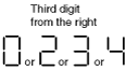
Confirm the third digit from the right.
|
![]() |
The fuel pulse signal from the cruise control switch is okay.
Go to the next step.
|
|
![]() |
Verify that the voltage of instrument cluster terminal 2J is 4.7—5.3 V.
• If the voltage is as specified, replace the instrument cluster.
• If the voltage is not as specified, inspect the following parts:
|
|||
4
|
Press and hold the ON/OFF button (cruise control switch) and confirm the third digit from the right.
|
![]() |
The fuel pulse signal from the cruise control switch is okay.
Go to the next step.
|
|
![]() |
Verify that the voltage of instrument cluster terminal 2J is 0—0.9 V.
• If the voltage is as specified, replace the instrument cluster.
• If the voltage is not as specified, inspect the following parts:
|
|||
5
|
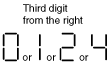
Press and hold the CANCEL button (cruise control switch) and confirm the third digit from the right.
|
![]() |
The fuel pulse signal from the cruise control switch is okay.
Go to the next step.
|
|
![]() |
Verify that the voltage of instrument cluster terminal 2J is 1.2—1.8 V.
• If the voltage is as specified, replace the instrument cluster.
• If the voltage is not as specified, inspect the following parts:
|
|||
6
|
Press and hold the SET/COAST button (cruise control switch) and confirm the third digit from the right.
|
![]() |
The fuel pulse signal from the cruise control switch is okay.
Go to the next step.
|
|
![]() |
Verify that the voltage of instrument cluster terminal 2J is 3.0—3.4 V.
• If the voltage is as specified, replace the instrument cluster.
• If the voltage is not as specified, inspect the following parts:
|
|||
7
|
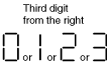
Press and hold the RES/ACCEL button (cruise control switch) and confirm the third digit from the right.
|
![]() |
The fuel pulse signal from the cruise control switch is okay.
Go to the next step.
|
|
![]() |
Verify that the voltage of instrument cluster terminal 2J is 4.0—4.5 V.
• If the voltage is as specified, replace the instrument cluster.
• If the voltage is not as specified, inspect the following parts:
|
Check code 63
Check code 63 |
Passenger seat belt reminder indicator flashing signal |
|||
---|---|---|---|---|
INSPECTION CONDITION |
DISPLAY |
ACTION |
||
After selecting check code 63, wait approx. 2 s.
|
![]() |
Passenger seat belt reminder indicator flashes three times.
|
Passenger seat belt reminder indicator is normal.
|
|
Except above
|
Replace the instrument cluster.
|