 |
am3zzn00000759
CAN SYSTEM DESCRIPTION
id094000101000
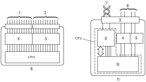
Mechanism of CAN System-Related Module
|
Component |
Function |
|
|---|---|---|
|
Electrical circuit
|
Supplies power to CPU and vicinity, and to input/output interface.
|
|
|
CPU
|
Computation processing block
|
Control function has been expanded, and when transmission is necessary, transmitted data is stored in a multiplex block. If a multiplex block receives a request to read stored data, transmitted data is read from the multiplex block.
|
|
Multiplex block
|
Transmits data received from bus line to computation processing block. In addition, sends transmitted data stored from computation processing block to bus line.
|
|
|
Input/Output interface
|
Electrically converts information signals from switches to, be input to CPU, and signals output from CPU for operating actuator or indicator lights.
|
|
am3zzn00000759
|
|
1
|
Input signal
|
|
2
|
Output signal
|
|
3
|
Connector
|
|
4
|
Input interface
|
|
5
|
Output interface
|
|
6
|
Conventional module
|
|
7
|
CAN harness (twisted pair)
|
|
8
|
Conventional wiring harness
|
|
9
|
Multiplex block
|
|
10
|
Computation processing block
|
|
11
|
CAN system-related module
|
Twisted Pair
am3zzn00000760
|
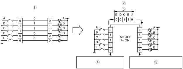
Time Division Multiplex
am3zzn00000761
|
|
1
|
Non-multiplex system
|
|
2
|
Time division multiplex system
|
|
3
|
Data
|
|
4
|
Each signal is transmitted one by one through the channel as it is received.
|
|
5
|
Each signal is output one by one as it is received from the channel.
|
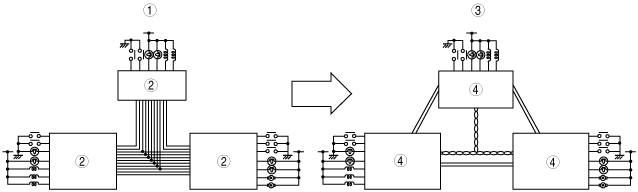
Vehicle CAN System
am3zzn00000762
|
|
1
|
Conventional system
|
|
2
|
Electrical module
|
|
3
|
CAN system
|
|
4
|
CAN system-related module
|
CAN Signal-Chart (HS-CAN)
|
Signal |
Multiplex module |
|||||||
|---|---|---|---|---|---|---|---|---|
|
PCM |
TCM (FS5A-EL) |
EHPAS control module |
DSC HU/CM |
Fuel additive control module (High power-Euro 4 only) |
Keyless control module |
Instrument cluster |
||
|
ABS HU/CM |
||||||||
|
Engine speed
|
OUT
|
IN
|
IN
|
IN
|
–
|
IN
|
IN
|
|
|
Vehicle speed
|
Except FS5A-EL
|
OUT
|
–
|
IN
|
–
|
–
|
IN
|
IN
|
|
FS5A-EL
|
IN
|
OUT
|
–
|
–
|
–
|
|||
|
ATX gear position/selector lever position (ATX)
|
Except FS5A-EL
|
OUT
|
–
|
IN
|
–
|
–
|
–
|
IN
|
|
FS5A-EL
|
IN
|
OUT
|
IN
|
IN
|
–
|
–
|
IN
|
|
|
CPP switch position (MTX)
|
IN
|
–
|
–
|
–
|
–
|
–
|
OUT
|
|
|
Engine torque
|
OUT
|
–
|
–
|
IN
|
–
|
–
|
–
|
|
|
–
|
||||||||
|
Accelerator pedal position
|
Except MZR-CD 1.6 (Y6)
|
OUT
|
IN
|
–
|
IN
|
–
|
–
|
–
|
|
MZR-CD 1.6 (Y6)
|
IN
|
–
|
–
|
OUT
|
||||
|
Brake pedal position
|
Except MZR-CD 1.6 (Y6)
|
OUT
|
IN
|
–
|
IN
|
–
|
–
|
–
|
|
MZR-CD 1.6 (Y6)
|
IN
|
–
|
–
|
OUT
|
||||
|
Transaxle specifications
|
OUT
|
–
|
–
|
IN
|
–
|
–
|
–
|
|
|
–
|
||||||||
|
Engine specifications
|
OUT
|
–
|
–
|
IN
|
–
|
–
|
–
|
|
|
–
|
||||||||
|
Engine control status
|
OUT
|
IN
|
–
|
–
|
–
|
–
|
–
|
|
|
Immobilizer-related information
|
OUT
|
–
|
–
|
–
|
–
|
IN
|
IN
|
|
|
IN
|
–
|
OUT
|
||||||
|
Engine coolant temperature
|
OUT
|
IN
|
–
|
–
|
–
|
–
|
IN
|
|
|
Travelled distance
|
OUT
|
–
|
–
|
–
|
–
|
–
|
IN
|
|
|
Fuel injection amount
|
OUT
|
–
|
–
|
–
|
–
|
–
|
IN
|
|
|
MIL on request
|
Except FS5A-EL
|
OUT
|
–
|
–
|
–
|
–
|
–
|
IN
|
|
FS5A-EL
|
IN
|
OUT
|
–
|
|||||
|
Generator warning light on request
|
OUT
|
–
|
–
|
–
|
–
|
–
|
IN
|
|
|
Tire circumference
|
With DSC
|
OUT
|
IN
|
–
|
IN
|
–
|
–
|
–
|
|
With ABS
|
IN
|
–
|
OUT
|
|||||
|
EHPAS control module malfunction
|
–
|
–
|
OUT
|
–
|
–
|
–
|
IN
|
|
|
Steering angle
|
IN
|
–
|
OUT
|
–
|
–
|
–
|
–
|
|
|
Brake system status (EBD/ABS/DSC)
|
IN
|
IN
|
–
|
OUT
|
–
|
–
|
–
|
|
|
Wheel speed (LF, RF, LR, RR)
|
IN
|
–
|
–
|
OUT
|
–
|
–
|
–
|
|
|
Brake system warning light on request
|
–
|
–
|
–
|
OUT
|
–
|
–
|
IN
|
|
|
ABS warning light on request
|
–
|
–
|
–
|
OUT
|
–
|
–
|
IN
|
|
|
DSC indicator light on request
|
With DSC
|
–
|
–
|
–
|
OUT
|
–
|
–
|
IN
|
|
With ABS
|
–
|
|||||||
|
DSC OFF light on request
|
With DSC
|
–
|
–
|
–
|
OUT
|
–
|
–
|
IN
|
|
With ABS
|
–
|
|||||||
|
Security light on request
|
–
|
–
|
–
|
–
|
–
|
OUT
|
IN
|
|
|
Keyless warning light on request
|
–
|
–
|
–
|
–
|
–
|
OUT
|
IN
|
|
|
Keyless indicator light on request
|
–
|
–
|
–
|
–
|
–
|
OUT
|
IN
|
|
|
Keyless warning buzzer on request
|
–
|
–
|
–
|
–
|
–
|
OUT
|
IN
|
|
|
Cruise control system-related information
|
Except MZR-CD 1.6 (Y6)
|
OUT
|
–
|
–
|
–
|
–
|
–
|
IN
|
|
MZR-CD 1.6 (Y6)
|
IN
|
OUT
|
||||||
|
FS5A-EL
|
OUT
|
IN
|
–
|
|||||
|
IN
|
OUT
|
|||||||
|
Fuel tank level
|
IN
|
–
|
–
|
–
|
IN
|
–
|
OUT
|
|
|
A/C on request
|
IN
|
–
|
–
|
–
|
–
|
–
|
OUT
|
|
|
Transaxle in reverse position
|
IN
|
–
|
–
|
–
|
–
|
–
|
OUT
|
|
|
Parking brake position
|
–
|
–
|
IN
|
IN
|
–
|
–
|
OUT
|
|
|
Brake fluid level
|
–
|
–
|
–
|
IN
|
–
|
–
|
OUT
|
|
|
Ambient temperature
|
IN
|
–
|
–
|
–
|
–
|
–
|
OUT
|
|
|
PTC heater on request
|
IN
|
–
|
–
|
–
|
–
|
–
|
OUT
|
|
|
Front wiper status
|
IN
|
–
|
–
|
–
|
–
|
–
|
OUT
|
|
|
TNS status
|
IN
|
–
|
–
|
–
|
–
|
–
|
OUT
|
|
|
Glow indicator light on request
|
OUT
|
–
|
–
|
–
|
–
|
–
|
IN
|
|
|
Engine oil pressure
|
OUT
|
–
|
–
|
–
|
–
|
–
|
IN
|
|
|
Generator load
|
OUT
|
–
|
–
|
–
|
–
|
–
|
IN
|
|
|
Generator control duty cycle
|
OUT
|
–
|
–
|
–
|
–
|
–
|
IN
|
|
|
Fuel additive system status (MZ-CD 1.6 (Y6) High power-Euro 4)
|
IN
|
–
|
–
|
–
|
OUT
|
–
|
–
|
|
CAN Signal-Chart (MS-CAN)
|
Signal |
Multiplex module |
|||||
|---|---|---|---|---|---|---|
|
Passenger junction box (PJB) |
Climate control unit |
SAS control module |
Audio unit (base module) |
Information display |
Instrument cluster |
|
|
Ambient temperature
|
OUT
|
IN
|
–
|
–
|
IN
|
IN
|
|
Front wiper status
|
OUT
|
IN
|
–
|
–
|
–
|
IN
|
|
Turn indicator light on request
|
OUT
|
–
|
–
|
–
|
–
|
IN
|
|
Security light on request
|
OUT
|
–
|
–
|
–
|
–
|
IN
|
|
Alarm on request
|
OUT
|
–
|
–
|
–
|
–
|
IN
|
|
Each door status
|
OUT
|
–
|
–
|
–
|
–
|
IN
|
|
Brake fluid level
|
OUT
|
–
|
–
|
–
|
–
|
IN
|
|
High-beam indicator light on request
|
OUT
|
–
|
–
|
–
|
–
|
IN
|
|
Transaxle in reverse position
|
OUT
|
–
|
–
|
–
|
–
|
IN
|
|
Parking brake position
|
OUT
|
–
|
–
|
–
|
–
|
IN
|
|
Rear window defroster on request
|
IN
|
OUT
|
–
|
–
|
–
|
–
|
|
OUT
|
IN
|
|||||
|
A/C on request
|
IN
|
OUT
|
–
|
–
|
–
|
–
|
|
OUT
|
–
|
IN
|
||||
|
PTC heater ON request
|
IN
|
OUT
|
–
|
–
|
–
|
–
|
|
OUT
|
–
|
IN
|
||||
|
A/C status display request
|
–
|
OUT
|
–
|
–
|
IN
|
IN
|
|
Buckle switch status
|
–
|
–
|
OUT
|
–
|
–
|
IN
|
|
Air bag system warning light on request
|
–
|
–
|
OUT
|
–
|
–
|
IN
|
|
Seat belt warning light on request
|
–
|
–
|
OUT
|
–
|
–
|
IN
|
|
Seat belt warning alarm on request
|
–
|
–
|
OUT
|
–
|
–
|
IN
|
|
Air bag system warning alarm on request
|
–
|
–
|
OUT
|
–
|
–
|
IN
|
|
Temperature unit
|
OUT
|
–
|
–
|
–
|
IN
|
–
|
|
–
|
IN
|
OUT
|
||||
|
INFO switch status
|
–
|
–
|
–
|
–
|
OUT
|
IN
|
|
Audio status display request
|
–
|
–
|
–
|
OUT
|
IN
|
–
|
|
Engine speed
|
IN
|
–
|
–
|
–
|
–
|
OUT
|
|
Vehicle speed
|
IN
|
IN
|
IN
|
IN
|
–
|
OUT
|
|
Engine coolant temperature
|
IN
|
IN
|
–
|
–
|
–
|
OUT
|
|
Key reminder switch position
|
IN
|
–
|
–
|
–
|
–
|
OUT
|
|
Ignition key position
|
–
|
–
|
–
|
IN
|
IN
|
OUT
|
|
Air bag system warning light status
|
–
|
–
|
IN
|
–
|
–
|
OUT
|
|
Drive information system data
|
–
|
–
|
–
|
–
|
IN
|
OUT
|
|
Generator load
|
IN
|
–
|
–
|
–
|
–
|
OUT
|
|
Generator control duty cycle
|
IN
|
–
|
–
|
–
|
–
|
OUT
|
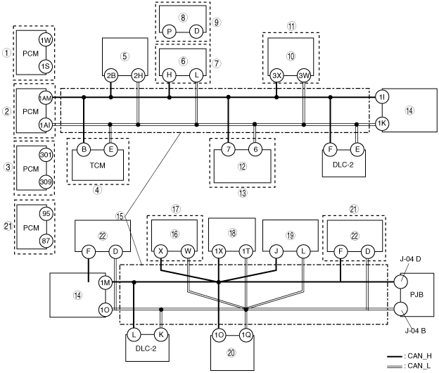
On-Board Diagnostic Function
Block diagram
am3zzn00001706
|
|
1
|
ZJ, ZY, Z6
|
|
2
|
LF, L3, L3 Turbo
|
|
3
|
MZ-CD 1.6 (YF)
|
|
4
|
FS5A-EL
|
|
5
|
EHPAS control module
|
|
6
|
ABS HU/CM
|
|
7
|
With ABS
|
|
8
|
DSC HU/CM
|
|
9
|
With DSC
|
|
10
|
Keyless control module
|
|
11
|
With advanced keyless system
|
|
12
|
Fuel additive control module
|
|
13
|
MZ-CD 1.6 (YF) High power-Euro 4
|
|
14
|
Instrument cluster
|
|
15
|
Twisted pair
|
|
16
|
Climate control unit
|
|
17
|
With full-auto air conditioner system
|
|
18
|
SAS control module
|
|
19
|
Information display
|
|
20
|
Audio unit (base module)
|
|
21
|
MZR-CD (RF Turbo)
|
|
22
|
Water heater unit
|
Failure detection function
Fail-safe function
Memory function
Self-malfunction diagnostic function
DTC table
|
DTC |
Malfunction location |
DTC output module |
|---|---|---|
|
U0001*1
|
CAN system communication error
|
PCM
|
|
U0073
|
CAN system communication error
|
• PCM
• TCM
• EHPAS control module
• Keyless control module
• Instrument cluster
|
|
SAS control module
|
||
|
U0100
|
Communication error to PCM
|
• TCM
• EHPAS control module
• Keyless control module
• Instrument cluster
|
|
U0101
|
Communication error to TCM
|
• PCM
• Instrument cluster
|
|
U0118*2
|
Communication error to fuel additive control module
|
PCM
|
|
U0121
|
Communication error to DSC HU/CM or ABS HU/CM
|
• PCM
• Instrument cluster
|
|
U0131
|
Communication error to EHPAS control module
|
Instrument cluster
|
|
U0140
|
Communication error to PJB
|
• Instrument cluster
• Climate control unit
|
|
U0151
|
Communication error to SAS control module
|
Instrument cluster
|
|
U0155
|
Communication error to instrument cluster
|
• PCM
• Climate control unit
|
|
U0164
|
Communication error to climate control unit
|
Information display
|
|
U0181
|
Communication error to instrument cluster
|
Information display
|
|
U0184
|
Communication error to audio unit (base module)
|
• Instrument cluster
• Climate control unit
• Information display
|
|
U0214
|
Communication error to keyless control module
|
Instrument cluster
|
|
U0323
|
Communication error to instrument cluster
|
Keyless control module
|
|
U0516
|
CAN system communication error
|
Climate control unit
|
|
U1900
|
Communication error to PCM
|
• ABS HU/CM
• DSC HU/CM
|
|
Communication error to instrument cluster
|
SAS control module
|
|
|
CAN system communication error
Abnormal message from other modules
|
PJB
|
|
|
Fuel additive control module*2
|
||
|
water heater unit
|
||
|
U2012
|
CAN system communication error
|
• ABS HU/CM
• DSC HU/CM
|
|
U2023
|
Abnormal message from PCM
|
EHPAS control module
|
|
Abnormal message from other modules
|
Keyless control module
|
|
|
U2202
|
Communication error to PCM
|
DSC HU/CM
|
|
U2516
|
CAN system communication error
|
Instrument cluster
|
|
Fuel additive control module*2
|
||
|
U2523
|
Communication error to PCM
|
• ABS HU/CM
• DSC HU/CM
|
|
16:Er12
|
CAN system communication error
|
Audio unit (base module)
|
|
17:Er11
|
Communication error to instrument cluster
|
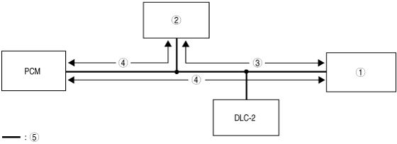
Narrowing down malfunction locations
Flowchart
am3zzn00000763
|
Example (PCM-related communication error)
1. DTCs for the PCM, DSC HU/CM and instrument cluster can be verified using the Mazda Modular Diagnostic System (M-MDS).
|
Module |
Displayed DTC |
Probable malfunction location |
|---|---|---|
|
PCM
|
U0073
|
PCM-related CAN system malfunction
|
|
U0121
|
Communication error between PCM and DSC HU/CM
|
|
|
U0155
|
Communication error between PCM and instrument cluster
|
|
|
DSC HU/CM
|
U0100
|
Communication error between DSC HU/CM and PCM
|
|
Instrument cluster
|
U0100
|
Communication error between instrument cluster and PCM
|
am3zzn00001707
|
|
1
|
Instrument cluster
|
|
2
|
DSC HU/CM
|
|
3
|
Communication normal
|
|
4
|
Communication error
|
|
5
|
Twisted pair
|
2. If there is a communication error between the instrument cluster and PCM, even if the communication between the DSC HU/CM and the instrument cluster is normal, it is probable that there is a malfunction in the PCM or PCM-related wiring harnesses.