CYLINDER BLOCK ASSEMBLY (II)
id011000504100
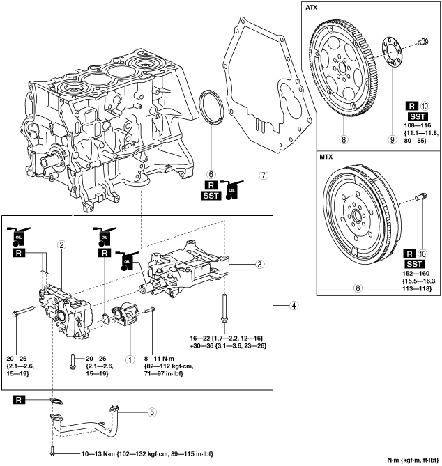
1. Assemble in the order indicated in the table.
|
1
|
Oil strainer
|
|
2
|
Oil pump
|
|
3
|
Balancer unit
|
|
4
|
Balancer component
|
|
5
|
Oil pipe
|
|
6
|
Rear oil seal
|
|
7
|
End plate
|
|
8
|
Dual-mass flywheel (MTX), drive plate (ATX)
|
|
9
|
Backing plate (ATX)
|
|
10
|
Dual-mass flywheel (MTX) / drive plate (ATX) installation bolt
|
Balancer Component Assembly Note
-
Caution
-
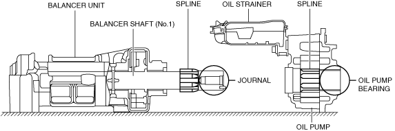
• If the balancer shaft (No.1) spline is scratched or damaged, the engagement with the oil pump spline could worsen and it may not be possible to assemble the oil pump. Therefore, be careful not to scratch or damage the spline.
• Because the balancer shaft (No.1) journal slides with oil pump bearing, if the journal is scratched or damaged, the bearing could become damaged. Therefore, be careful not to scratch or damage the journal.
1. Apply clean engine oil to a new oil strainer O-ring.
2. Assemble the oil strainer to the oil pump.
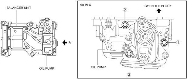
3. Assemble the oil pump to the balancer unit using the following procedure:
- (1) Verify that the balancer shaft (No.1) knock pin position is perpendicular to the cylinder block installation surface.
-
-
• If the knock pin position has deviated, rotate the balancer shaft (No.1) and correct.
- (2) Apply engine oil to the balancer shaft (No.1) journal area.
-
- (3) Align the heights of the balancer shaft (No.1) spline and oil pump spline and install the oil pump to the balancer unit.
-
-
Note
-
• The balancer shaft (No.1) spline and oil pump spline timing does not need to be matched.
- (4) Temporarily tighten the bolts until the seating surfaces of the oil pump installation bolts are completely seated.
-
4. Assemble the balancer component using the following procedure:
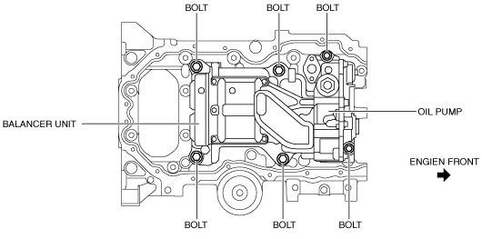
- (1) Install the oil pump and balancer unit to the cylinder block and temporarily tighten the seating face of the bolts shown in the figure until they are completely seated.
-
- (2) Tighten oil pump installation bolts in the order shown in the figure to the specified torque.
-
-
Tightening torque
-
20—26 N·m {2.1—2.6 kgf·m, 15—19 ft·lbf}
- (3) Tighten the balancer unit installation bolts in two steps in the order shown in the figure to the specified torque.
-
-
Tightening procedure
-
Step 1: 16—22 N·m {1.7—2.2 kgf·m, 12—16 ft·lbf}
Step 2: 30—36 N·m {3.1—3.6 kgf·m, 23—26 ft·lbf}
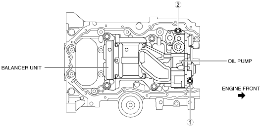
- (4) Tighten the oil pump installation bolts in the order shown in the figure.
-
-
Tightening torque
-
20—26 N·m {2.1—2.6 kgf·m, 15—19 ft·lbf}
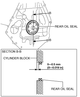
Rear Oil Seal Assembly Note
1. Apply clean engine oil to the inner surface of a new rear oil seal.
2. Insert the rear oil seal into the cylinder block by hand.
3. Tap the oil seal in evenly using the SST and a hammer.
-
Rear oil seal press on amount
-
0—0.5 mm {0—0.019 in} from edge surface of cylinder block
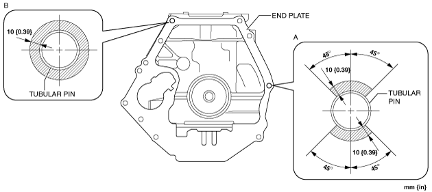
End Plate Assembly Note
1. After end plate assembly, crimp the parts A and B shown in the figure.
-
Crimp procedure
-
Crimp depth: 0.1—1.0 mm {0.004—0.039 in}
Crimp width: 0.5—10.0 mm {0.02—0.39 in}
Crimp locations: Part A is 1 or more on one-side within shaded area and part B is 2 or more within shaded areas
2. After crimping, verify that there is no damage and removal of the end plate.
Dual-mass Flywheel Installation Bolt Assembly Note [MTX]
1. Temporarily tighten the new bolts.
-
Note
-
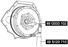
• If the dual-mass flywheel (secondary flywheel side) is not positioned properly, perform the following procedure to install it:
- (1) Temporarily tighten the new bolts to the position as shown in the figure.
-
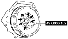
- (2) Install the SST (49 S120 710) to the dual-mass flywheel.
-
- (3) Rotate the dual-mass flywheel (secondary flywheel side) using the SST (49 S120 710), and then temporarily tighten the remaining new bolt after removing the SST (49 G033 102).
-
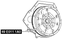
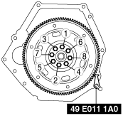
2. Hold the crankshaft using the SST (49 E011 1A0).
3. Tighten the new bolts in two or three passes in the order shown in the figure.
-
Tightening torque
-
152—160 N·m {15.5—16.3 kgf·m, 113—118 ft·lbf}
Drive Plate Installation Bolt Assembly Note [ATX]
1. Hold the crankshaft using the SST.
2. Tighten the new bolts in two or three passes in the order shown in the figure.
-
Tightening torque
-
108—116 N·m {11.1—11.8 kgf·m, 80—85 ft·lbf}