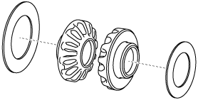
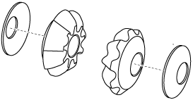
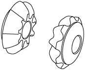
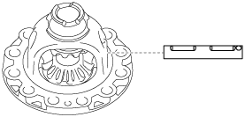
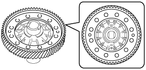
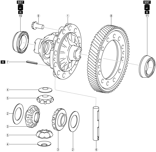
RING GEAR AND DIFFERENTIAL ASSEMBLY [FW6A-EL/FW6AX-EL]


id0517006641z3


Structural View

bfw2za00000204

1
Differential gear case
2
Thrust washer (selection)
3
Side gear
4
Thrust washer
5
Pinion gear
6
Pinion shaft
7
Roll pin
8
Ring gear
9
12 bolts (M13×1.0 bolt, length to approx. 26.2 mm {1.03 in})
10
Taper roller bearing (converter housing side)
(inner diameter approx. 45 mm {1.8 in})
11
Taper roller bearing (transaxle case side)
(inner diameter approx. 45 mm {1.8 in})


Assembly Procedure

1.  Assemble the thrust washers to the side gears.

azzjjw00001535
azzjjw00001536

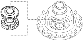
2.  Assemble the side gears which have the thrust washers assembled to them.

azzjjw00001537
azzjjw00001538

3.  Assemble the thrust washers to the pinion gears.

azzjjw00001539
azzjjw00001540

4.  Assemble the pinion gears which have the thrust washers assembled to them using the following procedure:

(1)  Assemble the pinion gears which have the thrust washers assembled to them.
azzjjw00001541
azzjjw00001542
(2)  Rotate the pinion gears so that the pinion shaft holes of the differential gear case and the pinion gears are aligned as shown in the figure.
Note
•  If the pinion shaft holes of the differential gear case and the pinion gears are not aligned, remove the pinion gears, change the side gears combination, and reassemble.
azzjjw00001543

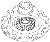
5.  Assemble the pinion shaft.

Caution
•  Assemble the pinion shaft so that the roll pin holes of the differential gear case and the pinion shaft are aligned.
azzjjw00001544
azzjjw00001545

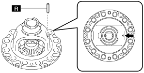
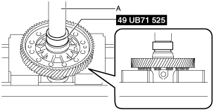
6.  Assemble a new roll pin to the position shown in the figure using a pin punch.

Caution
•  Assemble so that the end gap of the roll pin is positioned in the direction shown in the figure.
Note
•  Use a pin punch with an end outer diameter of 5 mm {0.197 in} or more, and within 8 mm {0.314 in}.
bfw2za00000703
azzjjw00001547
A  :–0.5—0.5 mm {–0.01—0.01 in}

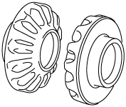
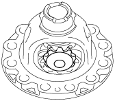
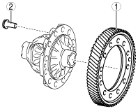
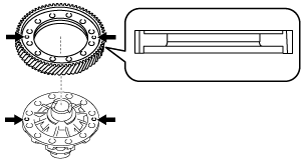
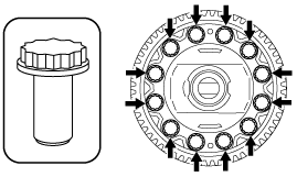
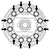
7.  Assemble the ring gear using the following procedure:

azzjjw00001000

1
Ring gear
2
12 bolts (M13×1.0 bolt, length to approx. 26.2 mm {1.03 in})

(1)  Assemble the ring gear.
Note
•  Assemble the ring gear so that the differential holes and ring gear holes shown in the figure are aligned.
azzjjw00001001
azzjjw00001002
(2)  Assemble and temporarily tighten the bolts to the positions shown in the figure.
Note
•  Bolt size: M13×1.0 bolt, length to approx. 26.2 mm {1.03 in}
azzjjw00001003
(3)  Secure the ring gear and differential in a vise.
Caution
•  Insert a protective plate between the vise and the part so as not to damage the part.
bfw2za00000704
A  :Vise
(4)  Tighten the bolts shown in the figure.
Note
•  Change the vise securing position of the ring gear and differential and tighten all of the bolts shown in the figure.
azzjjw00001005
Tightening torque
152—176 N·m {16—17 kgf·m, 113—129 ft·lbf}
(5)  Remove the ring gear and differential from the vise.
azzjjw00001006
A  :Vise

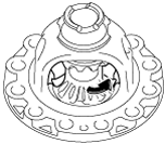
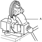
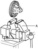
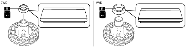
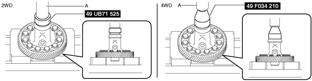
8.  Assemble the taper roller bearing (converter housing side) using the following procedure:

Note
•  Taper roller bearing size: Inner diameter approx. 45 mm {1.8 in} (2WD)
•  Taper roller bearing size: Inner diameter approx. 55 mm {2.2 in} (4WD)
(1)  Apply ATF (ATF FZ) to the engagement area of the taper roller bearing and differential.
(2)  Using the SST and press, assemble the taper roller bearing.
bfw2za00000205
bfw2za00000206
A  :Press

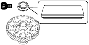
9.  Assemble the taper roller bearing (transaxle case side) using the following procedure:

Note
•  Taper roller bearing size: Inner diameter approx. 45 mm {1.8 in}
(1)  Apply ATF (ATF FZ) to the engagement area of the taper roller bearing and differential.
(2)  Using the SST and press, assemble the taper roller bearing.
bfw2za00000207
bfw2za00000705
A  :Press

10.  Perform the differential backlash measurement/adjustment. (See DIFFERENTIAL BACKLASH MEASUREMENT/ADJUSTMENT [FW6A-EL/FW6AX-EL].)