 |
bfw2za00000976
2-6 BRAKE CLEARANCE MEASUREMENT/ADJUSTMENT
id051700664800
Preparation Before Servicing
1. Print out the measurement/adjustment value input sheet. (See MEASUREMENT/ADJUSTMENT VALUE INPUT SHEET [EW6A-EL/EW6AX-EL].)(See MEASUREMENT/ADJUSTMENT VALUE INPUT SHEET [FW6A-EL/FW6AX-EL].)
2-6 Brake Clearance Measurement
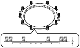
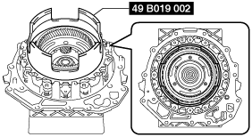
1. Set the end cover for the assembled part on the workbench as shown in the figure.
bfw2za00000976
|
2. Measure the retainer thickness of the springs and retainer component.
azzjjw00001169
|
3. Input the measured retainer thickness of the springs and retainer component into the measurement/adjustment value input sheet.
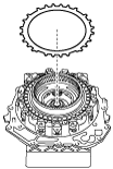
4. Assemble the retaining plate.
bfw2za00000977
|
bfw2za00000978
|
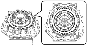
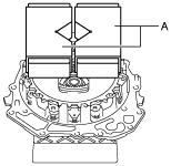
5. Install the SST.
bfw2za00000979
|
bfw2za00000980
|
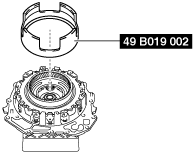
6. Place a 98—196 N {10.0—19.9 kgf, 23.0—44.0 lbf} weight on the SST.
bfw2za00000981
|
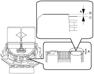
7. Measure distance A shown in the figure in four locations (each separated by 90°) and calculate the average value of distance A.
bfw2za00000982
|
8. Input the measured distance A and calculated distance A average value into the measurement/adjustment value input sheet.
9. Perform the following calculation to calculate the 2-6 brake clearance.
10. Input the calculated 2-6 brake clearance into the measurement/adjustment value input sheet.
11. Verify that the 2-6 brake clearance satisfies the specification.
12. Remove the weight on the SST.
bfw2za00000983
|
13. Remove the SST.
bfw2za00000979
|
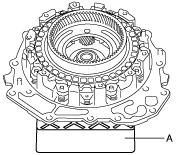
14. Take the end cover off the rubber plates.
azzjjw00001177
|
2-6 Brake Clearance Adjustment
1. Remove the weight on the SST.
bfw2za00000983
|
2. Remove the SST.
bfw2za00000979
|
3. Remove the retaining plate.
bfw2za00000977
|
4. Measure the thickness of the removed retaining plate.
5. Input the measured retaining plate thickness into the measurement/adjustment value input sheet.
6. Select the appropriate retaining plate from the following table:
|
Range* |
Selected retaining plate thickness |
|---|---|
|
Exceeds 3.550 mm {0.1398 in}, 3.650 mm {0.1437 in} or less
|
2.5 mm {0.098 in}
|
|
Exceeds 3.450 mm {0.1358 in}, 3.550 mm {0.1398 in} or less
|
2.4 mm {0.094 in}
|
|
Exceeds 3.350 mm {0.1319 in}, 3.450 mm {0.1358 in} or less
|
2.3 mm {0.091 in}
|
|
Exceeds 3.250 mm {0.1280 in}, 3.350 mm {0.1319 in} or less
|
2.2 mm {0.087 in}
|
|
Exceeds 3.150 mm {0.1240 in}, 3.250 mm {0.1280 in} or less
|
2.1 mm {0.083 in}
|
|
Exceeds 3.050 mm {0.1201 in}, 3.150 mm {0.1240 in} or less
|
2.0 mm {0.079 in}
|
|
Exceeds 2.950 mm {0.1161 in}, 3.050 mm {0.1201 in} or less
|
1.9 mm {0.075 in}
|
|
Exceeds 2.850 mm {0.1122 in}, 2.950 mm {0.1161 in} or less
|
1.8 mm {0.071 in}
|
|
Exceeds 2.750 mm {0.1083 in}, 2.850 mm {0.1122 in} or less
|
1.7 mm {0.067 in}
|
7. Assemble the selected retaining plate.
bfw2za00000977
|
bfw2za00000978
|
8. Perform the 2-6 brake clearance measurement from Step 5. (See 2-6 Brake Clearance Measurement.)