 |
bc61um00000001
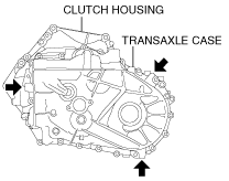
TRANSAXLE DISASSEMBLY
id051500175200
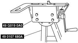
Step 1
1. Assemble the SST (49 G019 0A0) to the SST (49 0107 680A).
bc61um00000001
|
2. Assemble the MTX to the SST.
bd62zm00000001
|
3. Remove the parts around the MTX in the order shown in the figure.
bd62zm00000002
|
|
1
|
Breather
|
|
2
|
Neutral switch
|
|
3
|
Gasket
|
|
4
|
Plug
|
|
5
|
Gasket
|
|
6
|
Spring
|
|
7
|
Detent ball pin
|
|
8
|
Back-up light switch
|
|
9
|
Gasket
|
|
10
|
Oil level plug
|
|
11
|
Gasket
|
|
12
|
Drain plug
|
|
13
|
Gasket
|
|
14
|
Service hole plug
|
|
15
|
Gasket
|
|
16
|
Service hole plate
|
|
17
|
Shift control module
|
|
18
|
O-ring
|
|
19
|
Stud bolt
|
|
20
|
Oil seal
|
Step 2
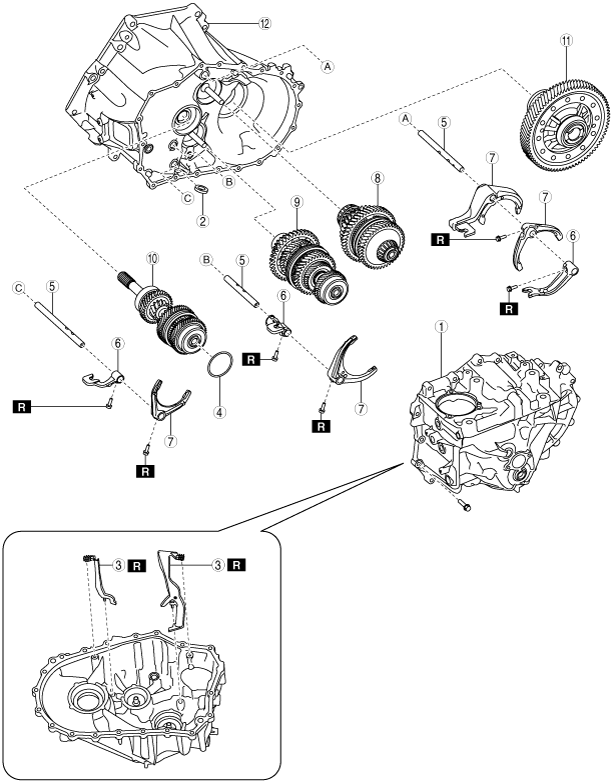
1. Disassemble the MTX in the order shown in the figure.
bd62zm00000003
|
|
1
|
Transaxle case component
|
|
2
|
Magnet
|
|
3
|
Oil path
|
|
4
|
Shim
|
|
5
|
Shift rod
|
|
6
|
Shift rod end
|
|
7
|
Shift fork
|
|
8
|
Secondary shaft No.2 component
|
|
9
|
Secondary shaft No.1 component
|
|
10
|
Primary shaft component
|
|
11
|
Differential
|
|
12
|
Clutch housing component
|
2. Remove the silicone sealant of the transaxle case component and clutch housing component, and clean all the parts.
Transaxle case component removal note
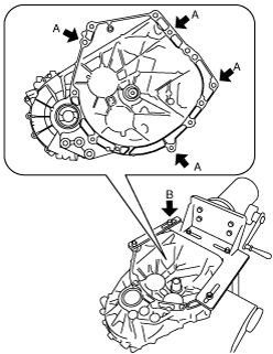
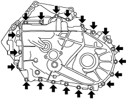
1. Remove the transaxle case installation bolts.
bd62zm00000178
|
2. Insert the bolt through service hole No.1 of the transaxle case, and assemble it to secondary shaft No.1 component.
bd62zm00000004
|
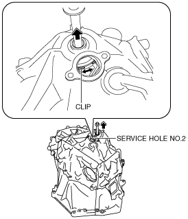
3. While pulling up the bolt assembled to secondary shaft No.1 component, turn the clip so that the clip opening is aligned with service hole No.2.
bd62zm00000005
|
4. Insert snap ring pliers into service hole No.2, widen the clip, and disconnect secondary shaft No.1 component from the transaxle case.
bd62zm00000006
|
5. Remove the bolt assembled to secondary shaft No.1 component.
6. Using a crow bar, pry the positions shown in the figure to remove the transaxle case from the clutch housing.
bd62zm00000007
|
Primary shaft component, secondary shaft No.1 component, secondary shaft No.2 component, differential removal note
1. Remove the primary shaft component, secondary shaft No.1 component, secondary shaft No.2 component, and the differential at the same time.
bd62zm00000008
|