 |
bc61um00000024
SECONDARY SHAFT NO.1 COMPONENT INSPECTION
id051500176200
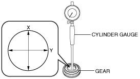
Gear Inspection
1. Inspect the gears for damage, wear, or loss.
2. Inspect the gears and synchronizer rings for damage and wear on contact surfaces.
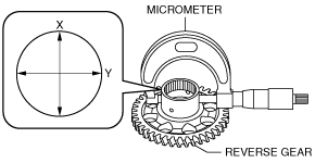
3. Measure the inner diameter of the gear using a cylinder gauge in X and Y directions as shown in the figure.
bc61um00000024
|
Inner diameter of gear
|
Measurement location |
Specification (mm {in}) |
Maximum (mm {in}) |
|---|---|---|
|
Secondary 3rd gear
|
43.413 {1.7092}
|
43.425 {1.7096}
|
|
Secondary 4th gear
|
57.015 {2.2447}
|
57.030 {2.2453}
|
|
Reverse gear
|
45.948 {1.8090}
|
45.955 {1.8093}
|
4. Measure the outer diameter of the reverse gear using the micrometer in X and Y directions as shown in the figure.
bd62zm00000094
|
Secondary Shaft No.1 Inspection
1. Inspect the spline for damage and wear.
2. Inspect the gear area for damage, wear, and loss.
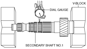
3. Measure the runout of the secondary shaft No.1.
bd62zm00000185
|
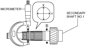
4. Measure the outer diameter of the secondary shaft No.1 using a micrometer. Measurement positions total four and are in the X and Y directions, at four points (A and B) as shown in the figure.
bd62zm00000186
|
Outer diameter of secondary shaft No.1
|
Measurement location |
Specification (mm {in}) |
Minimum (mm {in}) |
|---|---|---|
|
A: Secondary 3rd gear assembly part
|
43.358 {1.7070}
|
43.345 {1.7065}
|
|
B: Reverse gear assembly part
|
45.983 {1.8104}
|
45.975 {1.8100}
|
Synchronizer Ring Inspection
1. Inspect the teeth of the synchronizer ring for damage, wear, or loss.
2. Inspect the taper surface for wear or loss.
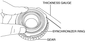
3. While holding the synchronizer ring and gear with your fingers as shown in the figure, measure the clearance of the synchronizer ring and gear side surface around the entire circumference using a thickness gauge.
bc61um00000027
|
Clearance between synchronizer ring and gear
|
Measurement location |
Specification (mm {in}) |
Minimum (mm {in}) |
|---|---|---|
|
Synchronizer ring (3GR)
|
1.145 {0.04508}
|
0.40 {0.01575}
|
|
Synchronizer ring (4GR)
|
1.145 {0.04508}
|
0.40 {0.01575}
|
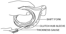
Clutch Hub Component Inspection
1. Inspect the clutch hub sleeve and clutch hub operation.
2. Inspect the spline for damage, wear or loss.
3. While holding the clutch hub sleeve and shift fork together with your hand as shown in the figure, measure the clearance between the shift fork and clutch hub sleeve groove using a thickness gauge.
bc61um00000028
|
Clearance between shift fork and clutch hub sleeve groove
|
Measurement location |
Specification (mm {in}) |
Maximum (mm {in}) |
|---|---|---|
|
Shift fork (3GR/4GR)
|
0.225 {0.00886}
|
0.40 {0.0157}
|