SECONDARY SHAFT NO.2 COMPONENT PREINSPECTION
id051500176400
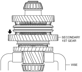
Secondary 1st Gear Thrust Clearance Inspection
1. Measure the secondary 1st gear thrust clearance using the following procedure:
- (1) Secure the secondary shaft No.2 component using a vice.
-
-
Caution
-
• Insert a protective plate between the vise and the part so as not to damage the part.
• Do not pinch the tapered roller bearing using a vice.
- (2) Set the dial gauge to the position of the arrow shown in the figure.
- (3) Move the secondary 1st gear in the axial direction and measure the secondary 1st gear thrust clearance.
-
-
• If it exceeds the maximum specification, inspect the secondary 1st gear and surrounding parts for damage and wear and replace the malfunctioning part.
-
Secondary 1st gear thrust clearance
-
Specification: 0.168 mm {0.00661 in}
Maximum: 0.250 mm {0.00984 in}
Secondary 2nd Gear Thrust Clearance Inspection
1. Measure the secondary 2nd gear thrust clearance using the following procedure:
- (1) Secure the secondary shaft No.2 component using a vice.
-
-
Caution
-
• Insert a protective plate between the vise and the part so as not to damage the part.
• Do not pinch the tapered roller bearing using a vice.
- (2) Set the dial gauge to the position of the arrow shown in the figure.
- (3) Move the secondary 2nd gear in the axial direction and measure the secondary 2nd gear thrust clearance.
-
-
• If it exceeds the maximum specification, inspect the secondary 2nd gear and surrounding parts for damage and wear and replace the malfunctioning part.
-
Secondary 2nd gear thrust clearance
-
Specification: 0.240 mm {0.00945 in}
Maximum: 0.312 mm {0.0123 in}
Reverse Idler Gear Thrust Clearance Inspection
1. Measure the reverse idler gear thrust clearance using the following procedure:
- (1) Secure the secondary shaft No.2 component using a vice.
-
-
Caution
-
• Insert a protective plate between the vise and the part so as not to damage the part.
• Do not pinch the tapered roller bearing using a vice.
- (2) Set the dial gauge to the position of the arrow shown in the figure.
- (3) Move the reverse idler gear in the axial direction and measure the reverse idler gear thrust clearance.
-
-
• If it exceeds the maximum specification, inspect the reverse idler gear and surrounding parts for damage and wear and replace the malfunctioning part.
-
Reverse idler gear thrust clearance
-
Specification: 0.20 mm {0.00787 in}
Maximum: 0.291 mm {0.0115 in}