OIL PUMP REMOVAL/INSTALLATION [SKYACTIV-D 2.2]
id0111s6800600
For Other Than Europe
-
Warning
-
• Hot engines and engine oil can cause severe burns. Turn off the engine and wait until it and the engine oil have cooled.
• A vehicle that is lifted but not securely supported on safety stands is dangerous. It can slip or fall, causing death or serious injury. Never work around or under a lifted vehicle if it is not securely supported on safety stands.
• Continuous exposure to USED engine oil has caused skin cancer in laboratory mice. Protect your skin by washing with soap and water immediately after working with engine oil.
-
Caution
-
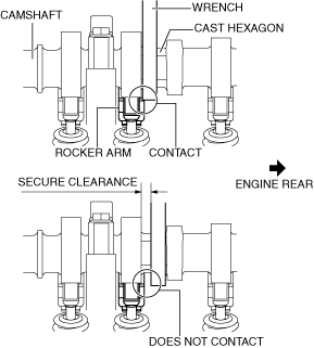
• If the camshaft is rotated with the timing chain removed and the piston at the top dead center position, the valve may contact the piston and the engine could be damaged. When rotating the camshaft with the timing chain removed, rotate it after lowering the piston from the top dead center position.
• When rotating the camshaft using a wrench on the cast hexagon, the wrench may contact the rocker arm and damage the rocker arm. To prevent damage to the rocker arm when holding the camshaft on the cast hexagon, use a wrench on the rear side of the engine as shown in the figure to secure a clearance between the cam.
-
Note
-
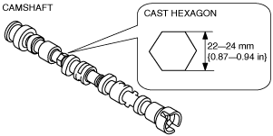
• Width at the cast hexagon of the camshaft is 22—24 mm {0.87—0.94 in}.
1. Disconnect the negative battery cable. (See NEGATIVE BATTERY CABLE DISCONNECTION/CONNECTION [SKYACTIV-D 2.2].)
2. Remove the engine cover. (See ENGINE COVER REMOVAL/INSTALLATION [SKYACTIV-D 2.2].)
3. Remove the front under cover No.2. (See FRONT UNDER COVER No.2 REMOVAL/INSTALLATION.)
4. Remove the front splash shield No.1 (RH). (See SPLASH SHIELD REMOVAL/INSTALLATION.)
5. Remove the drive belt. (See DRIVE BELT REMOVAL/INSTALLATION [SKYACTIV-D 2.2].)
6. Drain the engine oil. (See ENGINE OIL REPLACEMENT [SKYACTIV-D 2.2].)
7. Remove the oil pan. (See OIL PAN REMOVAL/INSTALLATION [SKYACTIV-D 2.2].)
8. Remove the fuel injectors. (See FUEL INJECTOR REMOVAL/INSTALLATION [SKYACTIV-D 2.2].)
9. Drain the engine coolant. (See ENGINE COOLANT REPLACEMENT [SKYACTIV-D 2.2].)
10. Remove the timing chain. (See TIMING CHAIN REMOVAL/INSTALLATION [SKYACTIV-D 2.2].)
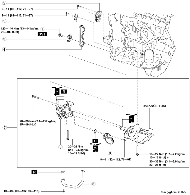
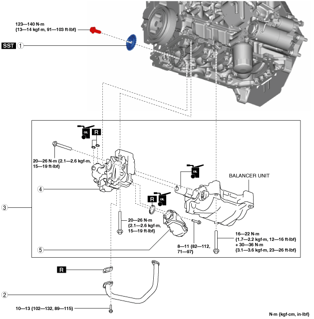
11. Remove in the order indicated in the table.
12. Install in the reverse order of removal.
13. Refill with the specified type and amount of the engine oil. (See ENGINE OIL REPLACEMENT [SKYACTIV-D 2.2].)
14. Refill the engine coolant. (See ENGINE COOLANT REPLACEMENT [SKYACTIV-D 2.2].)
15. Inspect for engine coolant leakage. (See ENGINE COOLANT LEAKAGE INSPECTION [SKYACTIV-D 2.2].)
16. Start the engine and confirm that there is no oil leakage.
-
• If there is oil leakage, repair or replace the applicable part.
17. Inspect the oil level. (See ENGINE OIL LEVEL INSPECTION [SKYACTIV-D 2.2].)
18. Inspect the oil pressure. (See OIL PRESSURE INSPECTION [SKYACTIV-D 2.2].)
|
1
|
Oil pump driven sprocket installation bolt
|
|
2
|
Oil pump chain tensioner
|
|
3
|
Oil pump driven sprocket
|
|
4
|
Oil pump chain
|
|
5
|
Oil pump chain guide
|
|
6
|
Oil pipe
|
|
7
|
Balancer component
|
|
8
|
Oil pump
|
|
9
|
Oil strainer
|
Oil pump chain removal note
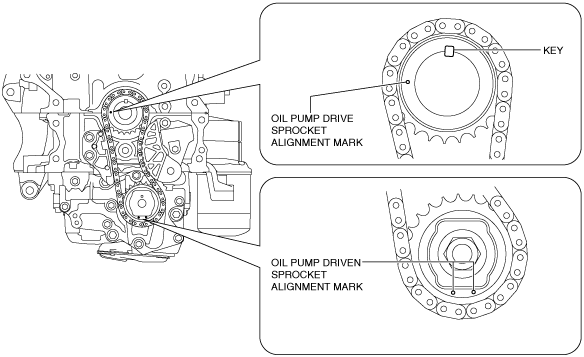
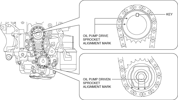
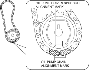
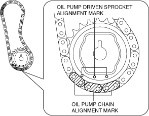
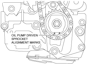
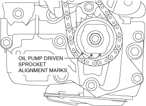
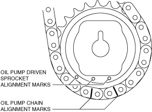
1. Verify that the oil pump driven sprocket alignment marks and key are aligned to the positions shown in the figure.
Type A
Type B
-
Note
-
• If they are not in the positions shown in the figure, rotate the crankshaft to set cylinder No.1 to top dead center (TDC).
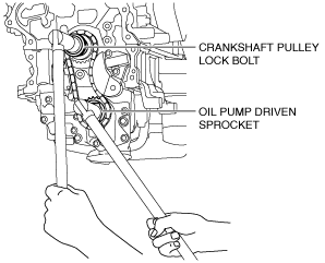
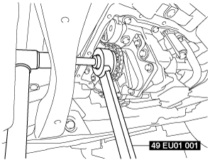
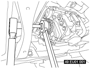
2. Temporarily assemble the crankshaft pulley lock bolt, and lock the oil pump against rotation as shown in the figure.
3. Slightly loosen the oil pump driven sprocket installation bolt.
-
Note
-
• At this stage, only loosen the oil pump driven sprocket installation bolt, do not remove it. Remove the bolt after removing the oil pump chain tensioner.
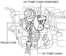
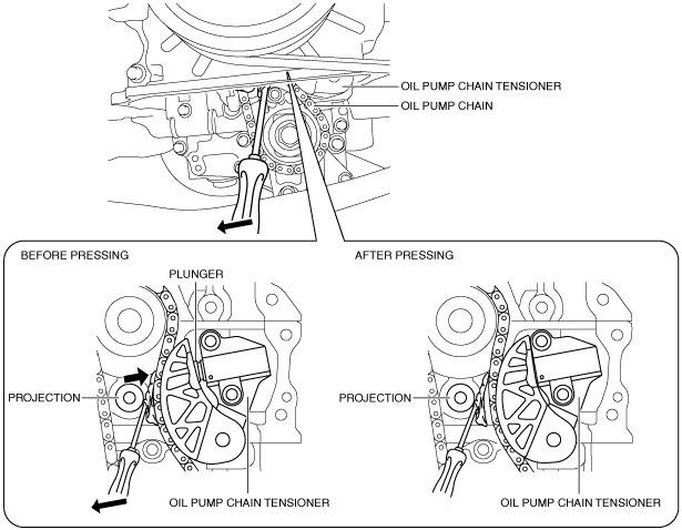
4. Set a cloth wrapped flathead screwdriver in the gap between the lower cylinder block projection and the oil pump chain as shown in the figure.
5. Move the screwdriver in the direction of the arrow and press the oil pump chain, and then press in the plunger of the oil pump chain tensioner.
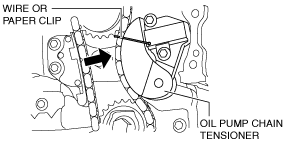
6. Insert a wire with an approx. diameter of 1.4 mm {0.055 in} or a paper clip into the body hole of the oil pump chain tensioner with the plunger pressed.
-
Note
-
• The wire or paper clip secures the plunger, and the tension can be released.
7. Remove the oil pump chain tensioner.
8. Remove the oil pump chain and oil pump driven sprocket as a single unit.
9. Remove the temporarily assembled crankshaft pulley lock bolt.
Oil pump, balancer unit installation note
-
Caution
-
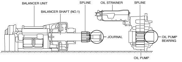
• If the balancer shaft (No.1) spline is scratched or damaged, the engagement with the oil pump spline could worsen and it may not be possible to assemble the oil pump. Therefore, be careful not to scratch or damage the spline.
• Because the balancer shaft (No.1) journal slides with oil pump bearing, if the journal is scratched or damaged, the bearing could become damaged. Therefore, be careful not to scratch or damage the journal.
1. Install the oil pump and balancer component using the following procedure:
- (1) Apply clean engine oil to a new oil strainer O-ring.
-
- (2) Assemble the oil strainer to the oil pump.
-
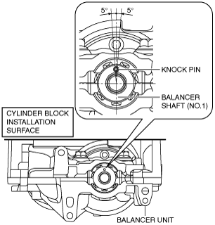
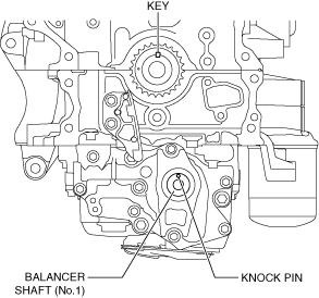
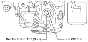
- (3) Verify that the balancer shaft (No.1) knock pin position is perpendicular to the cylinder block installation surface.
-
-
• If the knock pin position has deviated, rotate the balancer shaft (No.1) and correct.
- (4) Apply engine oil to the balancer shaft (No.1) journal area.
-
- (5) Align the heights of the balancer shaft (No.1) spline and oil pump spline and install the oil pump to the balancer unit.
-
-
Note
-
• The balancer shaft (No.1) spline and oil pump spline timing does not need to be matched.
- (6) Temporarily tighten the bolts until the seating surfaces of the oil pump installation bolts are completely seated.
-
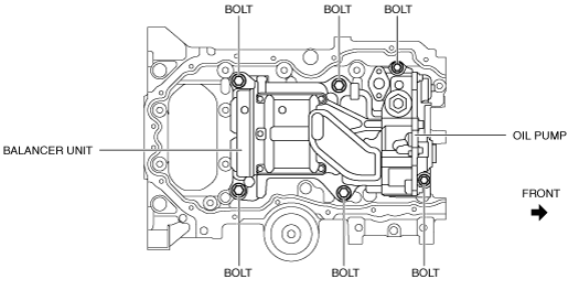
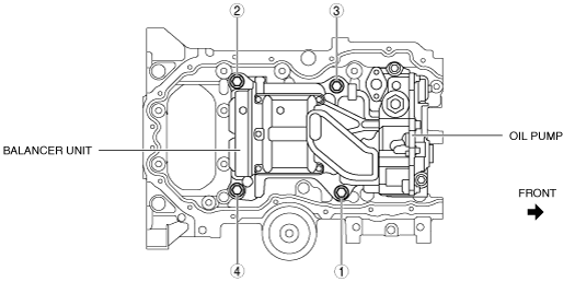
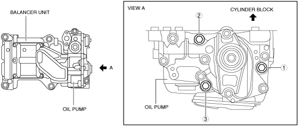
- (7) Install the oil pump and balancer unit to the cylinder block and temporarily tighten the seating face of the bolts shown in the figure until they are completely seated.
-
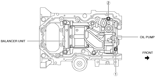
- (8) Tighten oil pump installation bolts in the order shown in the figure to the specified torque.
-
-
Tightening torque
-
20—26 N·m {2.1—2.6 kgf·m, 15—19 ft·lbf}
- (9) Tighten the balancer unit installation bolts in two steps in the order shown in the figure to the specified torque.
-
-
Tightening torque
-
First step: 16—22 N·m {1.7—2.2 kgf·m, 12—16 ft·lbf}
Second step: 30—36 N·m {3.1—3.6 kgf·m, 23—26 ft·lbf}
- (10) Tighten the oil pump installation bolts in the order shown in the figure.
-
-
Tightening torque
-
20—26 N·m {2.1—2.6 kgf·m, 15—19 ft·lbf}
Oil pump chain installation note
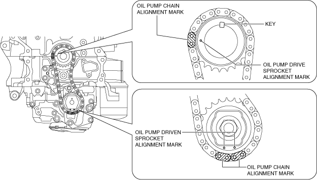
1. Verify that the key and knock pin are aligned to the positions shown in the figure.
-
• If they are not in the positions shown in the figure, rotate the crankshaft and balancer shaft (No.1) to set cylinder No.1 to top dead center (TDC).
-
Note
-
• When rotating the balancer shaft (No.1), temporarily assemble the oil pump driven sprocket and rotate while holding the sprocket with a hand.
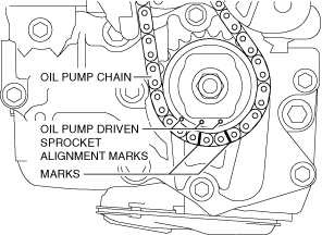
2. Align the oil pump chain alignment marks with the oil pump driven sprocket alignment marks.
Type A
Type B
3. Install the oil pump chain and oil pump driven sprocket as a single unit while aligning the alignment marks on each sprocket and oil pump chain as shown in the figure.
Type A
Type B
4. Temporarily tighten the oil pump driven sprocket installation bolt.
5. Install the oil pump chain tensioner.
-
Caution
-
• At this stage, do not remove the wire or paper clip installed to the oil pump chain tensioner.
6. Tighten the oil pump driven sprocket installation bolt using the following procedure:
- (1) Temporarily assemble the crankshaft pulley and crankshaft pulley lock bolt.
-
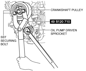
- (2) Install the SST shown in the figure and lock the oil pump against rotation. (See FRONT OIL SEAL REPLACEMENT [SKYACTIV-D 2.2].)
-
- (3) Tighten the oil pump driven sprocket installation bolt.
-
-
Tightening torque
-
123—140 N·m {13—14 kgf·m, 91—103 ft·lbf}
7. Remove the temporarily assembled crankshaft pulley and crankshaft pulley lock bolt.
8. Remove the wire or paper clip installed to the oil pump chain tensioner and apply tension to the oil pump chain.
-
• If a new oil pump chain tensioner is used, remove the installed stopper.
For Europe
-
Warning
-
• Hot engines and engine oil can cause severe burns. Turn off the engine and wait until it and the engine oil have cooled.
• A vehicle that is lifted but not securely supported on safety stands is dangerous. It can slip or fall, causing death or serious injury. Never work around or under a lifted vehicle if it is not securely supported on safety stands.
• Continuous exposure to USED engine oil has caused skin cancer in laboratory mice. Protect your skin by washing with soap and water immediately after working with engine oil.
1. Turn the steering wheel completely to the right.
2. Remove the front under cover No.2. (See FRONT UNDER COVER No.2 REMOVAL/INSTALLATION.)
3. Remove the front splash shield No.1 (RH). (See SPLASH SHIELD REMOVAL/INSTALLATION.)
4. Drain the engine oil. (See ENGINE OIL REPLACEMENT [SKYACTIV-D 2.2].)
5. Remove the oil pan. (See OIL PAN REMOVAL/INSTALLATION [SKYACTIV-D 2.2].)
6. Remove in the order indicated in the table.
7. Install in the reverse order of removal.
8. Refill with the specified type and amount of the engine oil. (See ENGINE OIL REPLACEMENT [SKYACTIV-D 2.2].)
9. Start the engine and confirm that there is no oil leakage.
-
• If there is oil leakage, repair or replace the applicable part.
10. Inspect the oil level. (See ENGINE OIL LEVEL INSPECTION [SKYACTIV-D 2.2].)
11. Inspect the oil pressure. (See OIL PRESSURE INSPECTION [SKYACTIV-D 2.2].)
|
1
|
Oil pump driven sprocket
|
|
2
|
Oil pipe
|
|
3
|
Balancer component
|
|
4
|
Oil pump
|
|
5
|
Oil strainer
|
Oil pump driven sprocket removal note
1. Rotate the crankshaft and align the oil pump driven sprocket alignment marks to the positions shown in the figure.
Type A
Type B
2. Place marks on the oil pump chain next to the oil pump driven sprocket alignment marks.
Type A
Type B
-
Note
-
• The marks will be used as alignment marks when installing the oil pump driven sprocket.
3. While locking the oil pump driven sprocket against rotation using the SST, remove the oil pump driven sprocket installation bolt.
4. Remove the oil pump driven sprocket.
Oil pump, balancer unit installation note
-
Caution
-
• If the balancer shaft (No.1) spline is scratched or damaged, the engagement with the oil pump spline could worsen and it may not be possible to assemble the oil pump. Therefore, be careful not to scratch or damage the spline.
• Because the balancer shaft (No.1) journal slides with oil pump bearing, if the journal is scratched or damaged, the bearing could become damaged. Therefore, be careful not to scratch or damage the journal.
1. Install the oil pump and balancer component using the following procedure:
- (1) Apply clean engine oil to a new oil strainer O-ring.
-
- (2) Assemble the oil strainer to the oil pump.
-
- (3) Verify that the balancer shaft (No.1) knock pin position is perpendicular to the cylinder block installation surface.
-
-
• If the knock pin position has deviated, rotate the balancer shaft (No.1) and correct.
- (4) Apply engine oil to the balancer shaft (No.1) journal area.
-
- (5) Align the heights of the balancer shaft (No.1) spline and oil pump spline and install the oil pump to the balancer unit.
-
-
Note
-
• The balancer shaft (No.1) spline and oil pump spline timing does not need to be matched.
- (6) Temporarily tighten the bolts until the seating surfaces of the oil pump installation bolts are completely seated.
-
- (7) Install the oil pump and balancer unit to the cylinder block and temporarily tighten the seating face of the bolts shown in the figure until they are completely seated.
-
- (8) Tighten oil pump installation bolts in the order shown in the figure to the specified torque.
-
-
Tightening torque
-
20—26 N·m {2.1—2.6 kgf·m, 15—19 ft·lbf}
- (9) Tighten the balancer unit installation bolts in two steps in the order shown in the figure to the specified torque.
-
-
Tightening torque
-
First step: 16—22 N·m {1.7—2.2 kgf·m, 12—16 ft·lbf}
Second step: 30—36 N·m {3.1—3.6 kgf·m, 23—26 ft·lbf}
- (10) Tighten the oil pump installation bolts in the order shown in the figure.
-
-
Tightening torque
-
20—26 N·m {2.1—2.6 kgf·m, 15—19 ft·lbf}
Oil pump driven sprocket installation note
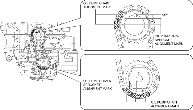
1. Verify that the knock pin is aligned to the position shown in the figure.
-
• If it is not in the position shown in the figure, rotate the balancer shaft (No.1) and adjust the knock pin position.
-
Note
-
• When rotating the balancer shaft (No.1), temporarily assemble the oil pump driven sprocket and rotate while holding the sprocket with a hand.
2. Align the oil pump chain alignment marks with the oil pump driven sprocket alignment marks.
Type A
Type B
3. Install the oil pump chain and oil pump driven sprocket as a single unit using the following procedure.
- (1) Press in the plunger of the oil pump chain tensioner as shown in the figure using a screwdriver wrapped in a cloth.
-
- (2) While pressing in the plunger of the oil pump chain tensioner, install the oil pump driven sprocket.
-
- (3) While locking the oil pump driven sprocket against rotation using the SST, tighten the oil pump driven sprocket installation bolt.
-
-
Tightening torque
-
123—140 N·m {13—14 kgf·m, 91—103 ft·lbf}