FUEL INJECTION CONTROL OPERATION [MZR 1.6]
id0140j7101900
Injection Timing
• There is synchronized fuel injection, which performs fuel injection by the setting of the crankshaft position, and non-synchronized fuel injection which performs fuel injection when the condition for fuel injection is met regardless of the crankshaft position.
Synchronized fuel injection
-
• The crankshaft rotation is synchronized by each intake and exhaust stroke of the cylinders, and fuel injection is performed by the fuel injection timing and the injection amount corresponding to the input signals of the following sensors.
-
― ECT sensor
― IAT sensor
― CKP sensor
― MAF sensor
Non-synchronized fuel injection
-
• The crankshaft rotation is not synchronized and fuel injection is performed by the injection timing and injection amount as triggered by the input signals of the following sensors.
-
― ECT sensor
― IAT sensor
― TP sensor
― MAF sensor
Relation between synchronized and non-synchronized fuel injection
-
• If synchronized and non-synchronized fuel injection happen to occur together, fuel is injected by adding the fuel injection timing of both.
Injection time
• The PCM calculates the fuel injection amount according to the engine operation conditions as the fuel injection time and energizes the fuel injectors.
Fuel injector energization time and operation conditions
-
• The fuel injectors cause an operation delay with the start of energization from the PCM. The PCM calculates the fuel injection time by adding the non-injection time (ineffective injection time) to the actual injection time (effective injection time), and energizes the fuel injectors for this time.
• The fuel injection time is based on the following formula:
Fuel injection time = effective injection time + ineffective injection time
Ineffective injection time
-
― The fuel injectors cause a delay in operation due to a delay in the build-up of operation current from coil inductance with the start of energization, and by the mass of the needle valve and plunger, and spring resistance. This delay is the ineffective injection time.
― The non-injection time is affected by the change in battery voltage. Accordingly, the PCM sets the non-injection time according to the battery voltage.
Effective injection time
-
― The fuel injector opening valve time which is the actual fuel injection time is called the effective injection amount.
Determination of effective injection time
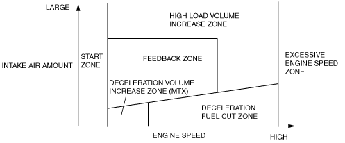
• The PCM divides the engine operation conditions into control zones according to engine speed and engine load and determines the effective injection time at each control zone to perform optimum air/fuel ratio control in all engine driving ranges.
Start zone
-
Purpose
-
• Improved engine startability
-
Control condition
-
• When engine speed is 500 rpm or less.
-
Determination of fuel injection time
-
• Determined according to engine coolant temperature and engine speed.
Excessive engine speed zone
-
Purpose
-
• Engine protection
-
Control conditions
-
• Engine speed is approx. 6,500 rpm or more
• All of the following conditions are met while the vehicle is stopped and engine coolant temperature is 40 °C {104 °F} or more.
-
― Engine speed of 1,500 rpm or more continues for 5 min.
― Engine speed of 3,000 rpm or more continues for 2 min.
― Engine coolant temperature is above 113 °C {235 °F} for 10 s.
-
Determination of fuel injection time
-
• Fuel injection time is set to 0 (fuel cut).
Deceleration volume increase zone (MTX)
-
Purpose
-
• Improved driveability
-
Control condition
-
• During Shifting
-
Determination of fuel injection time
-
• Determined according to engine speed
Deceleration Fuel Cut Zone
-
Purpose
-
• Improved fuel economy
• Prevents overheating of the catalytic converter
-
Control condition
-
• When the engine conditions are as follows
-
― Fully-closed throttle valve during deceleration (charging at fixed value or more)
― During driving under high load at engine speed of 1,000 rpm or more
-
Determination of fuel injection time method
-
• Fuel injection time is set to 0 (fuel cut).
High load volume increase zone
-
Purpose
-
• Improved driveability
-
Control condition
-
• Either the engine speed, charging efficiency or AP opening angle is a fixed value or more.
-
Determination of fuel injection time
-
• Corrections are added to the basic injection amount and the high load coefficient is calculated according to the engine speed, mass intake airflow amount and the throttle valve opening angle.
Feedback Zone
-
Purpose
-
• Improved fuel economy
• Improved exhaust gas purification
-
Control condition
-
• During engine operation other than high load volume increase zone and engine start zone.
-
Determination of fuel injection time
-
• During normal driving, the injection time is determined by the A/F sensor and HO2S and sets to the theoretical air/fuel ratio.
Calculation method table for fuel injection time
(*: Fuel injection time base, x: Correction for fuel injection time)
|
Contents
(Fuel injection time, calculation method, or determination method)
|
Control zone
|
 |
 |
 |
 |
 |
 |
 |
|
Injection time at start
|
Set value according to engine coolant temperature (low engine coolant temperature→long injection time)
|
*
|
|
|
|
|
|
|
|
Basic injection time
|
Basic injection time = charging efficiency x fuel flow coefficient
|
|
|
|
*
|
*
|
*
|
|
|
Fuel cut
|
Fuel injection time = 0
|
|
*
|
*
|
|
|
|
|
|
Ineffective injection time
|
Set time according to injector performance
|
*
|
|
|
*
|
*
|
*
|
|
|
Volume increase correction after engine start
|
Purpose: Maintains stability of engine speed just after engine start
Correction condition
• Specified time according to engine coolant temperature directly after engine start
Correction amount
• Low engine coolant temperature→large correction
• Low intake air temperature→large correction
|
×
|
|
|
|
|
×
|
|
|
A/F sensor
Feedback correction
|
Purpose: Controls air/fuel ratio to theoretical air/fuel ratio
Correction condition
• When engine coolant temperature is at set value or more.
Correction amount
• A/F sensor current value 0 mA or less→volume decrease correction
• A/F sensor current value 0 mA or more→volume increase correction
|
|
|
|
|
|
×
|
|
|
HO2S
Feedback correction
|
Purpose: Controls air/fuel ratio to theoretical air/fuel ratio
Correction condition
• When engine coolant temperature is at set value or more.
Correction amount
• HO2S voltage value 0.7 V or less→volume increase correction
• HO2S voltage value 0.7 V or more→volume decrease correction
|
|
|
|
|
|
×
|
|
|
D-range correction (ATX)
|
Purpose: Ensures engine speed stability during D-range shifting
Correction condition
• Throttle valve fully-closed and shifted into D-range
Correction amount
• Low engine coolant temperature→large correction
|
×
|
|
|
|
|
×
|
|
|
High load volume increase correction
|
Purpose: Improved engine output, decrease of exhaust gas temperature
Correction condition
• According to engine speed when the throttle valve opening angle is the fixed value or more, otherwise, according to engine speed and charging efficiency.
Correction amount
• High engine speed, high charging efficiency→large correction
|
|
|
|
|
×
|
|
|
|
Warm-up volume increase correction
|
Purpose: When engine coolant temperature is low, maintains combustion stability
Correction condition
• While at set engine coolant temperature
Correction amount
• High charging efficiency, low engine coolant temperature→large correction
|
|
|
|
|
|
×
|
|
|
Acceleration/deceleration volume increase correction
|
Purpose: Corrects fuel injection retard during acceleration/deceleration to ensure drive stability
Correction conditions
• Acceleration/deceleration (change in amount of charging efficiency) is at set value or more.
Correction amount
• Low engine coolant temperature→large correction
|
×
|
|
|
|
|
×
|
|
|
Deceleration volume increase correction
|
Purpose: Ensures stability of engine speed during recovery from fuel cut
Correction condition
• Recovery from deceleration fuel cut
Correction amount
• High engine speed→small correction
|
|
|
|
×
|
|
|
|
|
Learning correction
|
Purpose: Corrects deviation in air/fuel ratio from changes due to aged deterioration of mechanical devices
Correction condition
• Under any condition except purge control
Correction amount
• Learning value based on average of feedback correction value
|
|
|
|
|
×
|
×
|
|
|
Variable tumble correction
|
Purpose: Ensures combustion stability when variable tumble shutter valve is open
Correction condition
• Variable tumble shutter valve changes from closed to open
Correction amount
• Low engine coolant temperature→large correction
|
|
|
|
|
|
×
|
|
Fuel Cut
• Includes fuel cut under the following conditions except fuel cut at excessive engine speed according to engine operation and deceleration fuel cut.
Shift fuel cut (ATX)
-
Purpose
-
• To reduces shift shock during shifting
Execution condition
-
• During shifting (fuel cut of No.1 and No.4 cylinder)
Sensor damage fuel cut
-
Purpose
-
• To prevent engine damage from abnormal ignition due to a malfunction input of a cylinder identification or the engine speed signal.
-
Execution condition
-
• DTC stored for the following devices:
-
― CKP sensor
― CMP sensor
Dechoke Control
-
Purpose
-
• To improve engine starting startability when spark plugs are flooded.
-
Execution condition
-
• When cranking close to fully-open throttle valve