|
am3zzw00020020
FRONT DRIVE SHAFT (TRIPOD JOINT) DISASSEMBLY/ASSEMBLY [MTX]
id031300802604
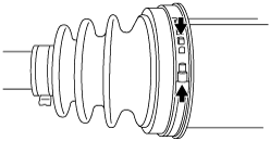
1. Disassemble in the order shown in the figure.
2. Assemble in the reverse order of disassembly.
am3zzw00020020
|
|
1
|
Boot band (transaxle side)
|
|
2
|
Outer ring
(See Outer Ring Disassembly Note.)
(See Outer Ring Assembly Note.)
|
|
3
|
Dust cover
(See Dust Cover Disassembly Note.)
(See Dust Cover Assembly Note.)
|
|
4
|
Snap ring
|
|
5
|
Bearing
(See Bearing Disassembly Note.)
(See Bearing Assembly Note.)
|
|
6
|
Snap ring
|
|
7
|
Tripod joint
|
|
8
|
Boot (transaxle side)
|
|
9
|
Dynamic damper
(See Dynamic Damper Assembly Note.)
|
|
10
|
Outer joint component
|
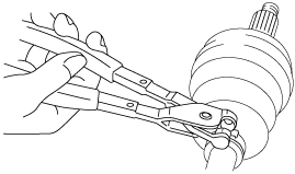
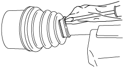
Boot Band (Transaxle Side) Disassembly Note
Large diameter side
1. Grasp the boot band at the point shown in the figure using pliers, and remove the band.
ac5jjw00003246
|
Small diameter side
1. Remove the boot band using end clamp pliers.
aatjjw00009759
|
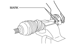
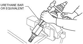
Outer Ring Disassembly Note
1. Place alignment marks on the shaft and outer ring.
am3uuw00011973
|
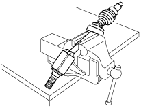
2. Secure the shaft in a vise.
aatjjw00009762
|
3. Lightly tap the outer ring evenly using a hammer and urethane bar or equivalent, and remove the outer ring from the shaft.
am3uuw00011974
|
4. Wipe off grease on the outer ring using a clean rag.
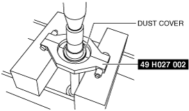
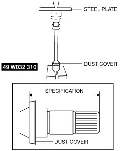
Dust Cover Disassembly Note
1. Remove the dust cover using a press and the SST.
am3uuw00011975
|
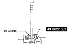
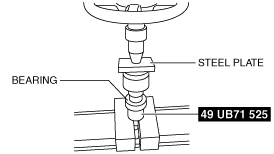
Bearing Disassembly Note
1. Remove the bearing using a press and SST.
am3uuw00011976
|
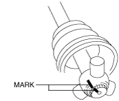
Snap Ring, Tripod Joint Disassembly Note
1. Place alignment marks on the shaft and tripod joint.
am3uuw00011977
|
2. Remove the snap ring using snap ring pliers.
atstjw00000054
|
3. Remove the tripod joint from the shaft.
4. Wipe off grease on the shaft and tripod joint using a clean rag.
Boot (Transaxle Side) Disassembly Note
1. Wrap vinyl tape around the spline area of the shaft to prevent damage to the boot.
azzzcw00000097
|
2. Remove the boot (transaxle side).
3. Wipe off grease on the boot (transaxle side) using a clean rag.
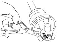
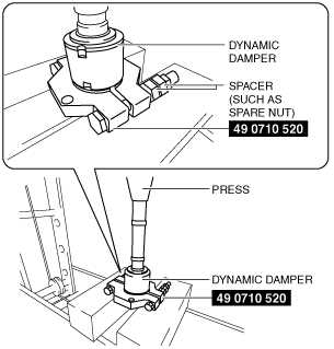
Dynamic Damper Disassembly Note
1. Remove the dynamic damper using the SST, spacers (such as spare nuts), and a press.
am2zzw00007267
|
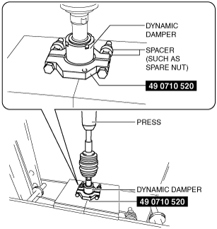
Dynamic Damper Assembly Note
1. Apply soapy water to the inside of the dynamic damper.
2. Assemble the dynamic damper using the SST, spacers (such as spare nuts), and a press.
am2zzw00012769
|
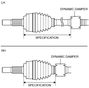
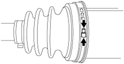
3. Verify that the installation position of the dynamic damper is within the specification.
am2zzw00007269
|
Specification
|
Engine type |
Installation position |
|
|---|---|---|
|
SKYACTIV-G 1.5
|
LH
|
271—277 mm {10.7—10.9 in}
|
|
RH
|
156.5—162.5 mm {6.162—6.397 in}
|
|
|
SKYACTIV-G 2.0
|
LH
|
271—277 mm {10.7—10.9 in}
|
|
RH
|
154—160 mm {6.07—6.29 in}
|
|
|
SKYACTIV-D 1.5
|
LH
|
271—277 mm {10.7—10.9 in}
|
|
RH
|
154—160 mm {6.07—6.29 in}
|
|
Boot (Transaxle Side) Assembly Note
1. Insert the shaft through the boot (transaxle side) with the vinyl tape left wrapped around the spline area of the shaft.
2. Remove the vinyl tape wrapped around the spline of the shaft.
Tripod Joint, Snap Ring Assembly Note
1. Assemble the tripod joint with the shaft and tripod joint alignment marks aligned.
am3uuw00011977
|
2. Assemble a new snap ring using snap ring pliers.
atstjw00000054
|
3. Verify that the snap ring is assembled correctly in the groove of the shaft.
Bearing Assembly Note
1. Assemble the new bearing using the SST and the press.
am3uuw00011979
|
Dust Cover Assembly Note
1. Assemble a new dust cover using the SST and the press.
am2zzw00007263
|
2. Verify that the installation position of the dust cover is within the specification.
Specification
|
Engine type |
Installation position |
|---|---|
|
SKYACTIV-G 1.5
|
83.5—84.7 mm {3.29—3.33 in}
|
|
SKYACTIV-G 2.0
|
87.7—88.9 mm {3.46—3.50 in}
|
|
SKYACTIV-D 1.5
|
87.7—88.9 mm {3.46—3.50 in}
|
Outer Ring Assembly Note
1. Apply the specified grease to the outer ring and boot (transaxle side).
Boot (transaxle side) grease amount
|
Engine type |
Grease amount |
|---|---|
|
SKYACTIV-G 1.5
|
110—130 g {3.89—4.58 oz}
|
|
SKYACTIV-G 2.0
|
110—130 g {3.89—4.58 oz}
|
|
SKYACTIV-D 1.5 (VIN: Except 3MZ)
|
114—124 g {4.03—4.37 oz}
|
|
SKYACTIV-D 1.5 (VIN: 3MZ)
|
110—130 g {3.89—4.58 oz}
|
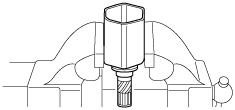
2. Secure the outer ring in the vise.
am3zzw00013719
|
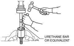
3. After aligning the shaft and outer ring alignment marks, lightly tap the tripod joint evenly using a hammer and urethane bar or equivalent, and insert the outer ring little by little while maintaining the shaft perpendicular.
am3zzw00013720
|
4. Assemble the boot (transaxle side) to the outer ring.
5. Set the drive shaft to the standard length.
Drive shaft (tripod joint) full length (standard)
|
Engine type |
Full length (standard) |
|
|---|---|---|
|
SKYACTIV-G 1.5
|
LH
|
677.6—687.6 mm {26.68—27.07 in}
|
|
RH
|
1002—1012 mm {39.45—39.84 in}
|
|
|
SKYACTIV-G 2.0
|
LH
|
655.1—665.1 mm {25.80—26.18 in}
|
|
RH
|
1019.3—1029.3 mm {40.130—40.523 in}
|
|
|
SKYACTIV-D 1.5
|
LH
|
657.1—667.1 mm {25.88—26.26 in}
|
|
RH
|
1,020.3—1,030.3 mm {40.170—40.563 in}
|
|
6. Release any trapped air from the boot by carefully lifting up the small end of the boot with a screwdriver wrapped in a clean rag.
aatjjw00009777
|
7. Verify that the drive shaft length is within the standard when the inside of the boot is at atmospheric pressure.
Boot Band (Transaxle Side) Assembly Note
Large diameter side
1. Grasp the boot band at the point shown in the figure using pliers and tighten the boot band.
am3zzw00013536
|
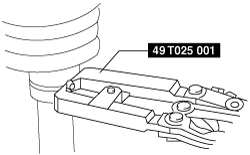
Small diameter side
1. Adjust opening A of the SST to the standard by rotating the adjustment bolt.
am3zzw00020274
|
2. Crimp the boot band using the SST.
am3uuw00009858
|
3. Verify that crimp B of the boot band is within the standard.
am3zzw00020275
|
4. Verify that the boot band does not protrude from the band assembly area.