FRONT DRIVE SHAFT (TRIPOD JOINT) DISASSEMBLY/ASSEMBLY [ATX]
id031300802605
-
Note
-
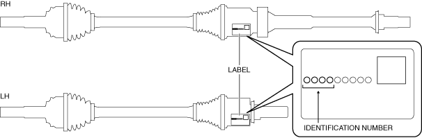
The drive shaft type can be read from the identification number indicated in the table below. (SKYACTIV-G 2.0)
•
Identification number and drive shaft type
|
Identification number
|
Type
|
|
FTC3
|
Type A
|
|
FTC8
|
Type B
|
|
FTU8
|
Type C
|
|
FTE8
|
Type D
|
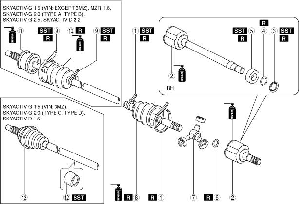
1. Disassemble in the order shown in the figure.
2. Assemble in the reverse order of disassembly.
|
1
|
Boot band (transaxle side)
|
|
2
|
Outer ring
|
|
3
|
Dust cover
|
|
4
|
Snap ring
|
|
5
|
Bearing
|
|
6
|
Snap ring
|
|
7
|
Tripod joint
|
|
8
|
Boot (transaxle side)
|
|
9
|
Boot band (wheel side)
|
|
10
|
Boot (wheel side)
|
|
11
|
Shaft and ball joint component
|
|
12
|
Dynamic damper (With dynamic damper)
|
|
13
|
Outer joint component
|
Boot Band (Transaxle Side) Disassembly Note [SKYACTIV-G 1.5, SKYACTIV-G 2.0 (Type C), SKYACTIV-D 1.5 (VIN: 3MZ)]
Large diameter side
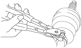
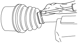
1. Grasp the boot band at the point shown in the figure using pliers, and remove the band.
Small diameter side
1. Remove the boot band using end clamp pliers.
Boot Band (Transaxle Side) Disassembly Note [MZR 1.6, SKYACTIV-D 1.5 (VIN: Except 3MZ), SKYACTIV-D 2.2]
1. Grasp the boot band at the point shown in the figure using pliers, and remove the band.
Boot Band (Transaxle Side) Disassembly Note [SKYACTIV-G 2.0 (Type A, Type B, Type D)]
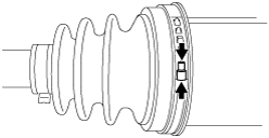
1. Using a flat chisel and hammer, lightly tap the lever of the boot band to disconnect the lock clip.
2. Remove the boot band using pliers.
Boot Band (Transaxle Side) Disassembly Note [SKYACTIV-G 2.5]
1. Remove the boot band using end clamp pliers.
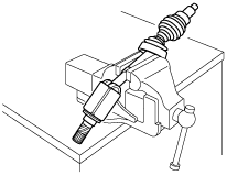
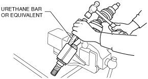
Outer Ring Disassembly Note
1. Place alignment marks on the shaft and outer ring.
-
Caution
-
• To prevent part damage, do not use a punch or similar tool to place alignment marks. Use paint.
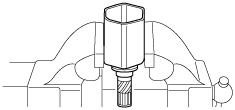
2. Secure the shaft in a vise.
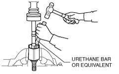
3. Lightly tap the outer ring evenly using a hammer and urethane bar or equivalent, and remove the outer ring from the shaft.
-
Caution
-
• When tapping the outer ring lightly using a hammer and urethane bar or equivalent, be careful not to scratch the roller area so as to prevent damage to the part.
4. Wipe off grease on the outer ring using a clean rag.
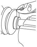
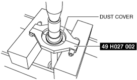
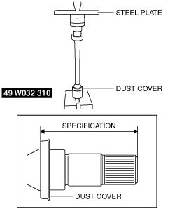
Dust Cover Disassembly Note
1. Remove the dust cover using a press and the SST.
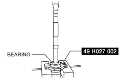
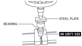
Bearing Disassembly Note
1. Remove the bearing using a press and SST.
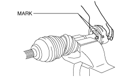
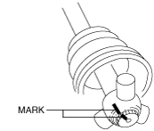
Snap Ring, Tripod Joint Disassembly Note
1. Place alignment marks on the shaft and tripod joint.
-
Caution
-
• To prevent damage to parts, do not use a punch or similar tool to place alignment marks. Use paint.
2. Remove the snap ring using snap ring pliers.
3. Remove the tripod joint from the shaft.
-
Caution
-
• When using the hammer and urethane bar or equivalent, be careful not to scratch the roller area so as to prevent damage to the part.
-
Note
-
• If the tripod joint cannot be removed from the shaft, lightly tap the tripod joint evenly using a hammer and urethane bar or equivalent, and remove the tripod joint from the shaft.
4. Wipe off grease on the shaft and tripod joint using a clean rag.
Boot (Transaxle Side) Disassembly Note
1. Wrap vinyl tape around the spline area of the shaft to prevent damage to the boot.
2. Remove the boot (transaxle side).
3. Wipe off grease on the boot (transaxle side) using a clean rag.
Boot Band (Wheel Side) Disassembly Note
1. Remove the boot band using end clamp pliers.
Boot (Wheel Side) Disassembly Note
1. Wrap vinyl tape around the spline area of the shaft to prevent damage to the boot.
2. Remove the boot (wheel side).
3. Wipe off grease on the boot (wheel side) and ball joint using a clean rag.
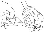
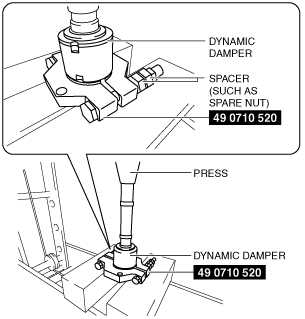
Dynamic Damper Disassembly Note
1. Remove the dynamic damper using the SST, spacers (such as spare nuts), and a press.
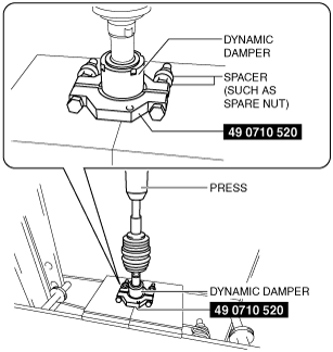
Dynamic Damper Assembly Note
1. Apply soapy water to the inside of the dynamic damper.
2. Assemble the dynamic damper using the SST, spacers (such as spare nuts), and a press.
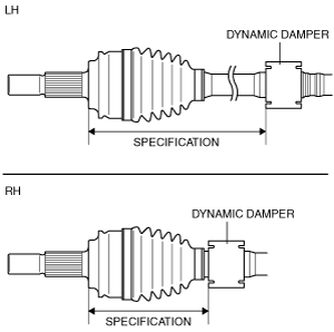
3. Verify that the installation position of the dynamic damper is within the specification.
Specification
|
Engine type
|
Specification
|
|
Except SKYACTIV-G 2.0 (Type C)
|
LH
|
271—277 mm {10.7—10.9 in}
|
|
RH
|
154—160 mm {6.07—6.29 in}
|
|
SKYACTIV-G 2.0 (Type C)
|
LH
|
223—229 mm {8.78—9.01 in}
|
|
RH
|
226.5—232.5 mm {8.918—9.153 in}
|
Boot (Wheel Side) Assembly Note
-
Note
-
• The boot shapes on the wheel side and the transaxle side are different. Do not assemble the wrong boot by mistake.
1. Insert the shaft through the boot (wheel side) with the vinyl tape left wrapped around the spline area of the shaft.
2. Apply the specified grease to the ball joint and boot (wheel side).
-
Note
-
• Apply the grease directly from the tube. Do not touch the grease directly with your hand.
Boot (wheel side) grease amount
|
Engine type
|
Grease amount
|
|
SKYACTIV-G 1.5
|
91—101 g {3.3—3.5 oz}
|
|
MZR 1.6
|
77—97 g {2.8—3.4 oz}
|
|
SKYACTIV-G 2.0 (Type A, Type D)
|
70—90 g {2.5—3.1 oz}
|
|
SKYACTIV-G 2.0 (Type B)
|
90—110 g {3.2—3.8 oz}
|
|
SKYACTIV-G 2.0 (Type C)
|
116—136 g {4.10—4.79 oz}
|
|
SKYACTIV-G 2.5
|
87—97 g {3.1—3.4 oz}
|
|
SKYACTIV-D 2.2
|
160—180 g {5.65—6.34 oz}
|
3. Assemble the boot (wheel side) to the ball joint.
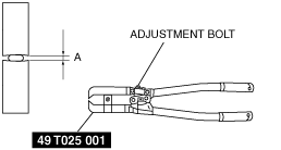
Boot Band (Wheel Side) Assembly Note
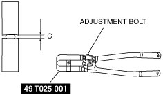
1. Adjust opening A of the SST to the standard by rotating the adjustment bolt.
Standard A
|
Engine type
|
Clearance
|
|
SKYACTIV-G 1.5
|
Large diameter side: Approx. 3.5 mm {0.14 in}
Small diameter side: Approx. 3.1 mm {0.12 in}
|
|
MZR 1.6
|
Approx. 4.5 mm {0.18 in}
|
|
SKYACTIV-G 2.0 (Type A, Type B, Type D)
|
Approx. 4.6 mm {0.18 in}
|
|
SKYACTIV-G 2.0 (Type C)
|
Large diameter side: Approx. 3.5 mm {0.14 in}
Small diameter side: Approx. 3.1 mm {0.12 in}
|
|
SKYACTIV-G 2.5
|
Large diameter side: Approx. 3.8 mm {0.15 in}
Small diameter side: Approx. 3.1 mm {0.12 in}
|
|
SKYACTIV-D 2.2
|
Approx. 4.5 mm {0.18 in}
|
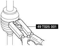
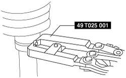
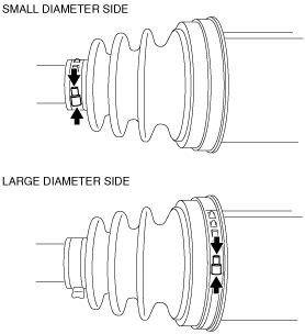
2. Crimp the boot band using the SST.
Large diameter side
Small diameter side
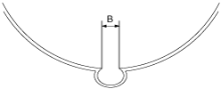
3. Verify that crimp B of the boot band is within the standard.
Standard B
|
Engine type
|
Clearance
|
|
SKYACTIV-G 1.5
|
1.5 mm {0.059 in} or less
|
|
MZR 1.6
|
2.0—3.0 mm {0.08—0.11 in}
|
|
SKYACTIV-G 2.0 (Type A, Type B, Type D)
|
1.2—4.0 mm {0.05—0.15 in}
|
|
SKYACTIV-G 2.0 (Type C)
|
1.5 mm {0.059 in} or less
|
|
SKYACTIV-G 2.5
|
Large diameter side: 1.8 mm {0.071 in} or less
Small diameter side: 1.5 mm {0.059 in} or less
|
|
SKYACTIV-D 2.2
|
2.0—3.0 mm {0.08—0.11 in}
|
-
• If crimp B exceeds the standard, decrease opening A of the SST and crimp the boot band again.
4. Verify that the boot band does not protrude from the band assembly area.
-
• If the boot band protrudes from the assembly area, replace it with a new one and repeat Steps 1 to 3.
Boot (Transaxle Side) Assembly Note
-
Note
-
• The boot shapes on the wheel side and the transaxle side are different. Do not assemble the wrong boot by mistake.
1. Insert the shaft through the boot (transaxle side) with the vinyl tape left wrapped around the spline area of the shaft.
2. Remove the vinyl tape wrapped around the spline of the shaft.
Tripod Joint, Snap Ring Assembly Note
1. Assemble the tripod joint with the shaft and tripod joint alignment marks aligned.
-
Caution
-
• When tapping the outer ring lightly using a hammer and urethane bar or equivalent, be careful not to scratch the roller area so as to prevent damage to the part.
-
Note
-
• If the tripod joint cannot be assembled to the shaft, lightly tap the tripod joint evenly using a hammer and urethane bar or equivalent, and assemble the tripod joint to the shaft.
2. Assemble a new snap ring using snap ring pliers.
3. Verify that the snap ring is assembled correctly in the groove of the shaft.
Bearing Assembly Note
1. Assemble the new bearing using the SST and the press.
Dust Cover Assembly Note
1. Assemble a new dust cover using the SST and the press.
2. Verify that the installation position of the dust cover is within the specification.
Specification
|
Engine type
|
Installation position
|
|
SKYACTIV-G 1.5 (VIN: Except 3MZ)
|
83.7—84.9 mm {3.30—3.34 in}
|
|
SKYACTIV-G 1.5 (VIN: 3MZ)
|
83.5—84.7 mm {3.29—3.33 in}
|
|
SKYACTIV-G 2.0
|
87.7—88.9 mm {3.46—3.50 in}
|
|
SKYACTIV-G 2.5
|
87.7—88.9 mm {3.46—3.50 in}
|
|
MZR 1.6
|
88.5—89.7 mm {3.49—3.53 in}
|
|
SKYACTIV-D 1.5
|
87.7—88.9 mm {3.46—3.50 in}
|
|
SKYACTIV-D 2.2
|
93.2—94.4 mm {3.67—3.71 in}
|
Outer Ring Assembly Note
1. Apply the specified grease to the outer ring and boot (transaxle side).
-
Note
-
• Apply the grease from the tube. Do not touch the grease directly with your hand.
Boot (transaxle side) grease amount
|
Engine type
|
Grease amount
|
|
SKYACTIV-G 1.5 (VIN: Except 3MZ)
|
87—97 g {3.1—3.4 oz}
|
|
SKYACTIV-G 1.5 (VIN: 3MZ)
|
110—130 g {3.89—4.58 oz}
|
|
MZR 1.6
|
102.3—115.3 g {3.609—4.067 oz}
|
|
SKYACTIV-G 2.0 (Type A)
|
135—155 g {4.77—5.46 oz}
|
|
SKYACTIV-G 2.0 (Type B)
|
LH: 140—160 g {4.94—5.64 oz}
RH: 130—150 g {4.59—5.29 oz}
|
|
SKYACTIV-G 2.0 (Type C)
|
110—130 g {3.89—4.58 oz}
|
|
SKYACTIV-G 2.0 (Type D)
|
LH: 140—160 g {4.94—5.64 oz}
RH: 135—155 g {4.77—5.46 oz}
|
|
SKYACTIV-G 2.5
|
124—134 g {4.38—4.72 oz}
|
|
SKYACTIV-D 1.5 (VIN: Except 3MZ)
|
114—124 g {4.03—4.37 oz}
|
|
SKYACTIV-D 1.5 (VIN: 3MZ)
|
110—130 g {3.89—4.58 oz}
|
|
SKYACTIV-D 2.2
|
155—175 g {5.47—6.17 oz}
|
2. Secure the outer ring in the vise.
3. After aligning the shaft and outer ring alignment marks, lightly tap the tripod joint evenly using a hammer and urethane bar or equivalent, and insert the outer ring little by little while maintaining the shaft perpendicular.
-
Caution
-
• When tapping the outer ring lightly using a hammer and urethane bar or equivalent, be careful not to scratch the roller area so as to prevent damage to the part.
• Be careful that dust and dirt do not get on the inside of the outer ring.
4. Assemble the boot (transaxle side) to the outer ring.
5. Set the drive shaft to the standard length.
Drive shaft (tripod joint) full length (standard)
|
Engine type
|
Full length (standard)
|
|
SKYACTIV-G 1.5 (VIN: Except 3MZ)
|
LH
|
671.5—681.5 mm {26.44—26.83 in}
|
|
RH
|
1,016.9—1,026.9 mm {40.036—40.429 in}
|
|
SKYACTIV-G 1.5 (VIN: 3MZ)
|
LH
|
663.6—673.6 mm {26.13—26.51 in}
|
|
RH
|
1015—1025 mm {39.97—40.35 in}
|
|
MZR 1.6
|
LH
|
683.3—693.3 mm {26.91—27.29 in}
|
|
RH
|
1,000.5—1,010.5 mm {39.390—39.783 in}
|
|
SKYACTIV-G 2.0 (Type A, Type D)
|
LH
|
660.5—670.5 mm {26.01—26.39 in}
|
|
RH
|
1,024.9—1,034.9 mm {40.351—40.744 in}
|
|
SKYACTIV-G 2.0 (Type B)
|
LH
|
659.1—669.1 mm {25.95—26.34 in}
|
|
RH
|
1,022.2—1,032.2 mm {40.245—40.637 in}
|
|
SKYACTIV-G 2.0 (Type C)
|
LH
|
655.1—665.1 mm {25.80—26.18 in}
|
|
RH
|
1019.3—1029.3 mm {40.130—40.523 in}
|
|
SKYACTIV-G 2.5
|
LH
|
659.6—669.6 mm {25.97—26.36 in}
|
|
RH
|
1,021—1,031 mm {40.20—40.59 in}
|
|
SKYACTIV-D 1.5
|
LH
|
654.6—664.6 mm {25.78—26.16 in}
|
|
RH
|
1,020.3—1,030.3 mm {40.170—40.563 in}
|
|
SKYACTIV-D 2.2
|
LH
|
647.3—657.3 mm {25.49—25.87 in}
|
|
RH
|
1,028.3—1,038.3 mm {40.485—40.877 in}
|
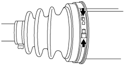
6. Release any trapped air from the boot by carefully lifting up the small end of the boot with a screwdriver wrapped in a clean rag.
-
Note
-
• Do not damage the boot. Verify that there is no grease leakage.
• If the boot is deformed, it may not be possible to perform the full-length adjustment of the shaft.
7. Verify that the drive shaft length is within the standard when the inside of the boot is at atmospheric pressure.
-
• If not within the standard, repeat from Step 5.
Boot Band (Transaxle Side) Assembly Note [SKYACTIV-G 1.5, SKYACTIV-G 2.0 (Type C), SKYACTIV-G 2.5, SKYACTIV-D 1.5 (VIN: 3MZ)]
SKYACTIV-G 1.5 (large diameter side), SKYACTIV-G 2.0 (Type C) (large diameter side), SKYACTIV-D 1.5 (large diameter side)
1. Grasp the boot band at the point shown in the figure using pliers and tighten the boot band.
SKYACTIV-G 1.5 (small diameter side), SKYACTIV-G 2.0 (Type C) (small diameter side), SKYACTIV-G 2.5, SKYACTIV-D 1.5 (small diameter side)
1. Adjust opening C of the SST to the standard by rotating the adjustment bolt.
Standard C
|
Engine type
|
Clearance
|
|
SKYACTIV-G 1.5 (VIN: Except 3MZ)
|
Approx. 2.0 mm {0.079 in}
|
|
SKYACTIV-G 1.5 (VIN: 3MZ)
|
Approx. 4.5 mm {0.18 in}
|
|
SKYACTIV-G 2.0 (Type C)
|
Approx. 4.5 mm {0.18 in}
|
|
SKYACTIV-G 2.5
|
Large diameter side: Approx. 3.8 mm {0.15 in}
Small diameter side: Approx. 3.1 mm {0.12 in}
|
|
SKYACTIV-D 1.5
|
Approx. 4.5 mm {0.18 in}
|
2. Crimp the boot band using the SST.
Large diameter side
Small diameter side
3. Verify that crimp D of the boot band is within the standard.
Standard D
|
Engine type
|
Clearance
|
|
SKYACTIV-G 1.5 (VIN: Except 3MZ)
|
0.8 mm {0.03 in} or less
|
|
SKYACTIV-G 1.5 (VIN: 3MZ)
|
2.0—3.0 mm {0.08—0.11 in}
|
|
SKYACTIV-G 2.0 (Type C)
|
2.0—3.0 mm {0.08—0.11 in}
|
|
SKYACTIV-G 2.5
|
Large diameter side: 1.8 mm {0.071 in} or less
Small diameter side: 1.5 mm {0.059 in} or less
|
|
SKYACTIV-D 1.5
|
2.0—3.0 mm {0.08—0.11 in}
|
-
• If crimp D exceeds the standard, decrease opening C of the SST and crimp the boot band again.
4. Verify that the boot band does not protrude from the band assembly area.
-
• If the boot band protrudes from the assembly area, replace it with a new one and repeat Steps 1 to 3.
Boot Band (Transaxle Side) Assembly Note [MZR 1.6, SKYACTIV-D 1.5 (VIN: Except 3MZ), SKYACTIV-D 2.2]
1. Grasp the boot band at the point shown in the figure using pliers and tighten the boot band.
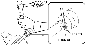
Boot Band (Transaxle Side) Assembly Note [SKYACTIV-G 2.0 (Type A, Type B, Type D)]
-
Warning
-
• Your hands could be injured while assembling the boot band. Therefore always wear gloves.
1. Apply rust prevention oil to the inside of the boot band.
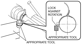
2. Lock the boot band against rotation using an appropriate tool as shown in the figure.
-
Caution
-
• Do not put the boot band back to its original position after bending it using pliers because it will damage the boot band.
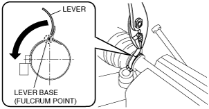
3. Using a pair of pliers, grip the lever at the base (fulcrum point) and rotate it in the direction of the arrow.
-
Caution
-
• If the lever flips back by reactive force, press it back again a maximum of only three times to prevent damage to the boot band.
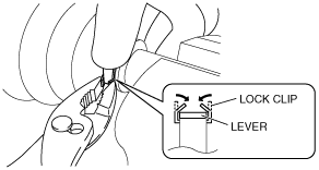
4. Hold the rotated lever with a finger and temporarily secure the lock clip by squeezing it with a pair of pliers.
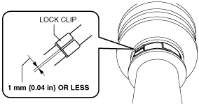
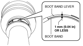
5. Lightly tap the lock clip with a hammer until the gap in the lock clip is 1 mm {0.04 in} or less.
6. After assembling the boot band, perform the following verification.
-
• The boot band does not protrude from the band assembly area.
• The lever is not deformed.
• The boot and boot band are not damaged.
• The gap between the boot band and the boot band lever is
1 mm {0.04 in} or less.
-
― If there is any malfunction, replace with a new part.