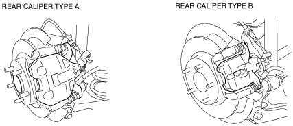
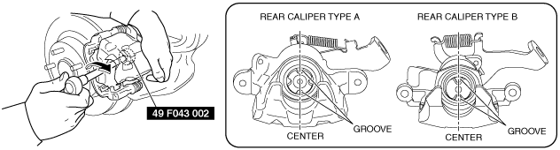
Note
• Verify the shape of the caliper shown in the figure to determine type A or B.
am3zzw00015895
|
DISC PAD (REAR) REPLACEMENT
id041100800300
Without Electric Parking Brake
am3zzw00015895
|
1. Remove the wheel and tire. (See WHEEL AND TIRE REMOVAL/INSTALLATION.)
2. Remove in the order indicated in the table.
3. Install in the reverse order of removal.
4. After installation, pump the brake pedal a few times and inspect the following:
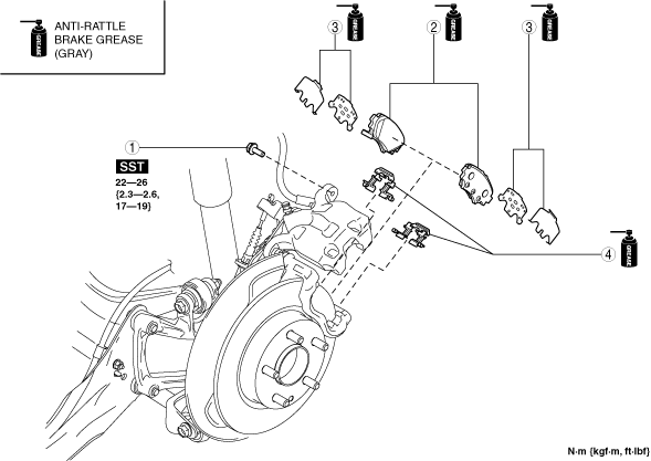
Rear caliper type A
am3zzw00019748
|
|
1
|
Caliper installation bolt
|
|
2
|
Disc pad
|
|
3
|
Shim
|
|
4
|
Guide plate
|
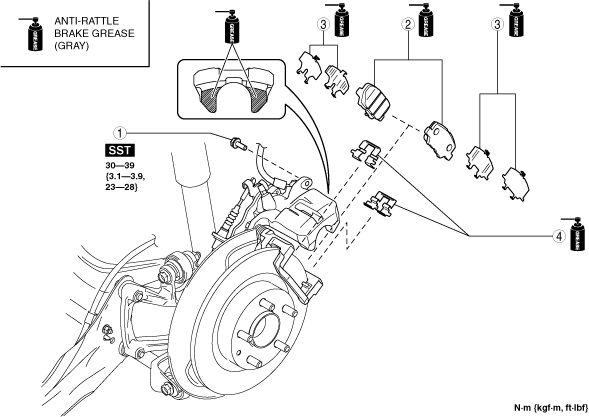
Rear caliper type B
am3zzw00020285
|
|
1
|
Caliper installation bolt
|
|
2
|
Disc pad
|
|
3
|
Shim
|
|
4
|
Guide plate
|
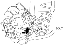
Caliper installation bolt removal note
1. Remove the caliper installation bolt shown in the figure and lift up the caliper.
am3uuw00010862
|
Caliper installation bolt installation note
1. Clean the exposed area of the piston.
2. Rotate the piston clockwise slowly using the SST and push the piston completely until the piston grooves are in the position shown in the figure.
am3zzw00015896
|
3. Return the caliper to the original position and install the caliper installation bolt.
With Electric Parking Brake
1. Switch to the maintenance mode. (See MAINTENANCE MODE.)
2. Disconnect the negative battery cable. (See NEGATIVE BATTERY CABLE DISCONNECTION/CONNECTION [SKYACTIV-G 1.5, SKYACTIV-G 2.0, SKYACTIV-G 2.5].) (See NEGATIVE BATTERY CABLE DISCONNECTION/CONNECTION [SKYACTIV-D 1.5].) (See NEGATIVE BATTERY CABLE DISCONNECTION/CONNECTION [SKYACTIV-D 2.2].)
3. Remove the wheel and tire. (See WHEEL AND TIRE REMOVAL/INSTALLATION.)
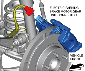
4. Disconnect the electric parking brake motor gear unit connector.
am3zzw00019750
|
5. Remove in the order indicated in the table.
6. Install in the reverse order of removal.
7. End the maintenance mode. (See MAINTENANCE MODE.)
8. After installation, pump the brake pedal a few times and inspect the following:
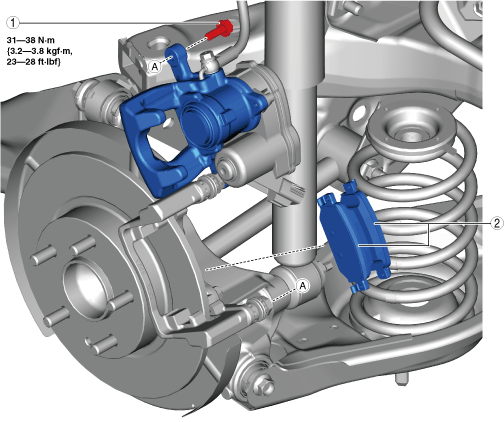
am3zzw00019751
|
|
1
|
Bolt
(See Bolt Removal Note.)
|
|
2
|
Disc pad
|
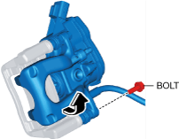
Bolt Removal Note
1. Remove the bolt shown in the figure and lift up the caliper.
am3zzw00019752
|
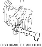
Disc Pad, Bolt Installation Note
1. Clean the exposed area of the piston.
2. Push the piston in using the commercially available disc brake expand tool.
am3zzw00019753
|
3. Install the disc pads to the mounting support.
4. Return the caliper to the original position and install the bolt.
am3zzw00019754
|