REAR BRAKE (DISC) REMOVAL/INSTALLATION
id041100800500
-
Caution
-
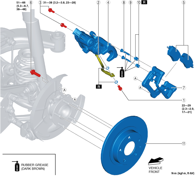
• The rear brake hose gasket has been established as a specialized part. If a gasket other than the specialized part is used, it could result in brake fluid leakage. Therefore, always use the specialized gasket for the rear brake hose.
• Brake fluid will damage painted surfaces. Be careful not to spill any on painted surfaces. In addition, if there is any brake fluid on the wiring harness, the wire insulation may corrode causing a malfunction such as a short circuit. If brake fluid gets on a painted surface or wiring harness, wash and flush it off completely with water immediately.
Without Electric Parking Brake
-
Note
-
• To remove/install the following parts, set aside the brake caliper with the brake hose connected and suspend it using a cable.
-
― Disc plate
― Mounting support
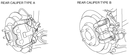
• Verify the shape of the caliper shown in the figure to determine type A or B.
1. Remove the wheel and tire. (See WHEEL AND TIRE REMOVAL/INSTALLATION.)
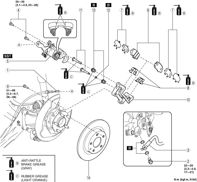
2. Remove in the order indicated in the table.
3. Install in the reverse order of removal.
4. After installation, add brake fluid, bleed the air, and inspect for fluid leakage. (See BRAKE FLUID AIR BLEEDING.)
5. Pump the brake pedal a few times and inspect the following:
-
― The disc pad projection is securely installed to the piston groove
― Parking brake lever stroke
― Brake drag
Rear caliper type A
|
1
|
Rear parking brake cable
|
|
2
|
Bolt
|
|
3
|
Brake hose
|
|
4
|
Bolt
|
|
5
|
Caliper*1
|
|
6
|
Disc pad
|
|
7
|
Shim
|
|
8
|
Guide plate
|
|
9
|
Bolt
|
|
10
|
Mounting support
|
|
11
|
Slide pin
|
|
12
|
Dust boot
|
|
13
|
Disc plate
|
*1 :When removing/installing a caliper, disconnect/connect the brake hose.
Rear caliper type B
|
1
|
Rear parking brake cable
|
|
2
|
Bolt
|
|
3
|
Brake hose
|
|
4
|
Bolt
|
|
5
|
Caliper*1
|
|
6
|
Disc pad
|
|
7
|
Shim
|
|
8
|
Guide plate
|
|
9
|
Bolt
|
|
10
|
Mounting support
|
|
11
|
Slide pin
|
|
12
|
Bushing
|
|
13
|
Dust boot
|
|
14
|
Disc plate
|
*1 :When removing/installing a caliper, disconnect/connect the brake hose.
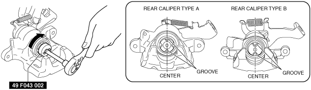
Caliper installation note
1. Clean the exposed area of the piston.
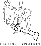
2. Rotate the piston clockwise slowly using the SST and push the piston completely until the piston grooves are in the position shown in the figure.
3. Install the caliper.
Rear parking brake cable installation note
1. Install the rear parking brake cable to the rear caliper.
2. Verify that the outer end tabs of the rear parking brake cable is securely engaged with the bracket.
With Electric Parking Brake
-
Note
-
• When in maintenance mode, the clearance between the disc pad and the disc plate expands.
• When the maintenance mode is completed, perform the electric parking brake automatic adjustment.
• With the electric parking brake automatic adjustment, the electric parking brake motor gear unit operation time is longer than normal.
1. Switch to the maintenance mode. (See MAINTENANCE MODE.)
2. Disconnect the negative battery cable. (See NEGATIVE BATTERY CABLE DISCONNECTION/CONNECTION [SKYACTIV-G 1.5, SKYACTIV-G 2.0, SKYACTIV-G 2.5].) (See NEGATIVE BATTERY CABLE DISCONNECTION/CONNECTION [SKYACTIV-D 1.5].) (See NEGATIVE BATTERY CABLE DISCONNECTION/CONNECTION [SKYACTIV-D 2.2].)
3. Remove the wheel and tire. (See WHEEL AND TIRE REMOVAL/INSTALLATION.)
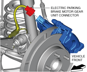
4. Disconnect the electric parking brake motor gear unit connector.
5. Remove in the order indicated in the table.
6. Install in the reverse order of removal.
7. End the maintenance mode. (See MAINTENANCE MODE.)
8. After installation, add brake fluid, bleed the air, and inspect for fluid leakage. (See BRAKE FLUID AIR BLEEDING.)
9. After installation, pump the brake pedal a few times and inspect the following:
-
― The disc pad projection is securely installed to the piston groove
― Brake drag
|
1
|
Bolt
|
|
2
|
Brake hose
|
|
3
|
Bolt
|
|
4
|
Caliper*1
|
|
5
|
Disc pad component
|
|
6
|
Bolt
|
|
7
|
Mounting support
|
|
8
|
Slide pin
|
|
9
|
Slide pin (with bushing)
|
|
10
|
Dust boot
|
|
11
|
Disc plate
|
*1 :When removing/installing a caliper, disconnect/connect the brake hose.
Caliper installation note
1. Clean the exposed area of the piston.
2. Push the piston in using the commercially available disc brake expand tool.
-
Caution
-
• If the piston is pushed into the caliper while rotating the piston, the caliper internal parts could be damaged. Be careful not to rotate the piston when pushing the piston into the caliper.
3. Install the caliper.