Note
• Tighten the brake pipe flare nut using any commercially available flare nut wrench.
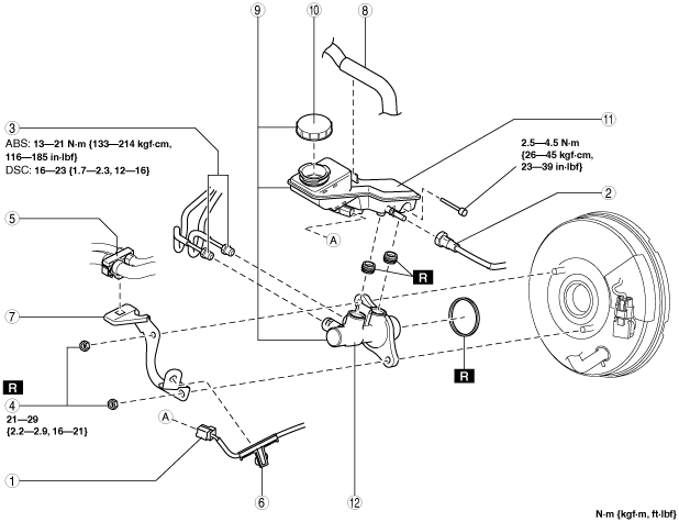
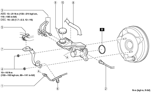
• Verify the shape of the master cylinder shown in the figure to determine type A or B.
am3zzw00015873
|
MASTER CYLINDER REMOVAL/INSTALLATION [L.H.D.]
id041100801350
am3zzw00015873
|
1. Disconnect the negative battery cable. (See NEGATIVE BATTERY CABLE DISCONNECTION/CONNECTION [MZR 1.6].) (See NEGATIVE BATTERY CABLE DISCONNECTION/CONNECTION [SKYACTIV-G 1.5, SKYACTIV-G 2.0, SKYACTIV-G 2.5].) (See NEGATIVE BATTERY CABLE DISCONNECTION/CONNECTION [SKYACTIV-D 1.5].) (See NEGATIVE BATTERY CABLE DISCONNECTION/CONNECTION [SKYACTIV-D 2.2].)
2. For SKYACTIV-D 1.5 or SKYACTIV-D 2.2, remove the battery. (See BATTERY REMOVAL/INSTALLATION [SKYACTIV-D 1.5].) (See BATTERY REMOVAL/INSTALLATION [SKYACTIV-D 2.2].)
3. Remove in the order indicated in the table.
4. Install in the reverse order of removal.
5. After installation, add brake fluid, bleed the air, and inspect for fluid leakage. (See BRAKE FLUID AIR BLEEDING.)
MASTER CYLINDER TYPE A
am3zzw00015874
|
|
1
|
Brake fluid level sensor connector
|
|
2
|
Clutch reserve hose (MTX)
|
|
3
|
Brake pipe
|
|
4
|
Nut
|
|
5
|
Hose holder
|
|
6
|
Wiring harness
|
|
7
|
Bracket
|
|
8
|
Vacuum hose
|
|
9
|
Master cylinder
|
|
10
|
Cap
|
|
11
|
Brake fluid reserve tank
|
|
12
|
Cylinder component
|
MASTER CYLINDER TYPE B
am3zzw00015875
|
|
1
|
Brake fluid level sensor connector
|
|
2
|
Clutch reserve hose (MTX)
|
|
3
|
Brake pipe
|
|
4
|
Nut
|
|
5
|
Hose holder
|
|
6
|
Wiring harness
|
|
7
|
Bracket
|
|
8
|
Vacuum hose
|
|
9
|
Master cylinder
|
|
10
|
Cap
|
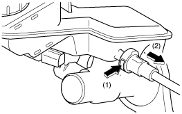
Clutch Reserve Hose Removal Note (MTX)
1. Disconnect the clutch reserve hose in the order shown in the figure.
am3uuw00010883
|
Clutch Reserve Hose Installation Note (MTX)
1. Insert the clutch reserve hose into the master cylinder.
2. Pull the clutch reserve hose to verify that it does not come off, and reinsert it completely.