am3zzn00004711
|
ABS HU/CM
id041300183400
Outline
am3zzn00004711
|
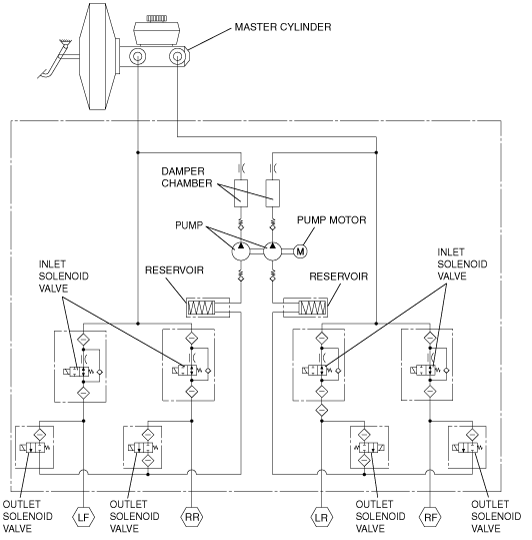
ABS HU Part Purpose/Function
ABS HU Part Construction
Function of main component parts
|
Part name |
Function |
|---|---|
|
Inlet solenoid valve
|
• Adjusts the fluid pressure in each brake system according to ABS CM signals.
|
|
Outlet solenoid valve
|
• Adjusts the fluid pressure in each brake system according to ABS CM signals.
|
|
Reservoir
|
• Temporarily holds the brake fluid from the caliper piston to ensure smooth pressure reduction.
|
|
Pump
|
• Returns brake fluid held in the reservoir back to the master cylinder.
|
|
Pump motor
|
• Operates the pump according to ABS CM signals.
|
Hydraulic circuit diagram
am3zzn00004869
|
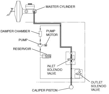
ABS HU Part Operation
During normal braking
Solenoid valve operation table
|
Inlet solenoid valve |
Outlet solenoid valve |
Pump motor, pump |
||||||
|---|---|---|---|---|---|---|---|---|
|
LF |
RF |
LR |
RR |
LF |
RF |
LR |
RR |
|
|
OFF (open)
|
OFF (closed)
|
OFF
|
||||||
Hydraulic circuit diagram
am3zzn00004713
|
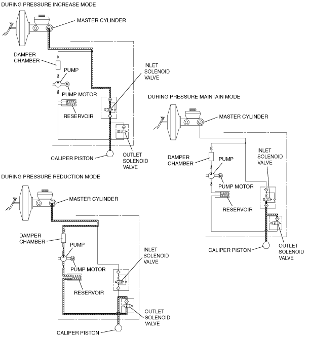
During ABS and EBD control
Solenoid valve operation table
|
|
Inlet solenoid valve |
Outlet solenoid valve |
Pump motor, pump |
||||||
|---|---|---|---|---|---|---|---|---|---|
|
LF |
RF |
LR |
RR |
LF |
RF |
LR |
RR |
||
|
During pressure increase mode
|
OFF (open)
|
OFF (closed)
|
OFF
|
||||||
|
During pressure maintain mode
|
ON (closed)
|
OFF (closed)
|
OFF
|
||||||
|
During pressure reduction mode
|
ON (closed)
|
ON (open)
|
ON
|
||||||
Hydraulic circuit diagram
am3zzn00004714
|
ABS CM Part Function
Function table
|
Function name |
Contents |
|---|---|
|
ABS control function
|
• Controls brake fluid pressure when braking to maintain directional stability, ensure steerability, and reduce stopping distance.
|
|
EBD control function
|
• Constantly controls proper distribution of brake fluid pressure to the front and rear wheels according to vehicle load, road surface, and vehicle speed conditions to prevent early lock-up of the rear wheels.
|
|
CAN communication function
|
• Outputs the vehicle wheel-speed signal and ABS system warning control data via CAN lines.
|
|
On-board diagnostic system
|
• Main components of the ABS control system have a self-diagnosis function. In case a malfunction occurs, warning lights illuminate to alert the driver, and at the same time, a DTC is stored in the ABS HU/CM.
• When a malfunction is determined as a result of the on-board diagnostic test, system control is disabled or limited to prevent any dangerous situation while driving.
|