 |
ac5wzn00000240
DYNAMIC STABILITY CONTROL (DSC)
id041500104600
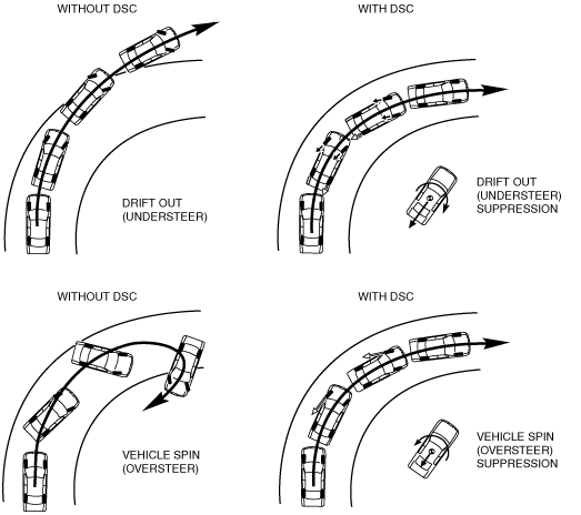
Outline
DSC operation outline
Results of DSC operation
ac5wzn00000240
|
Structural View
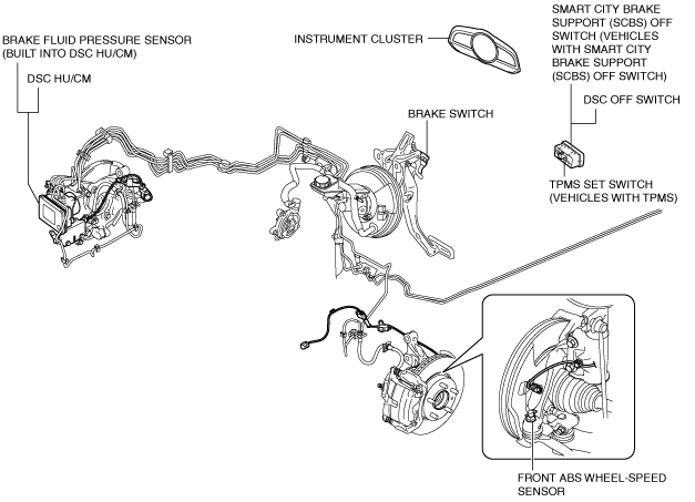
Vehicle front side (L.H.D.)
am3zzn00006208
|
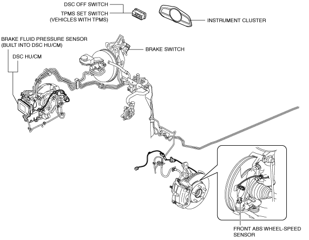
Vehicle front side (R.H.D.)
am3zzn00006209
|
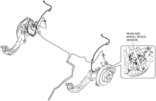
Vehicle rear side
am3uun00003048
|
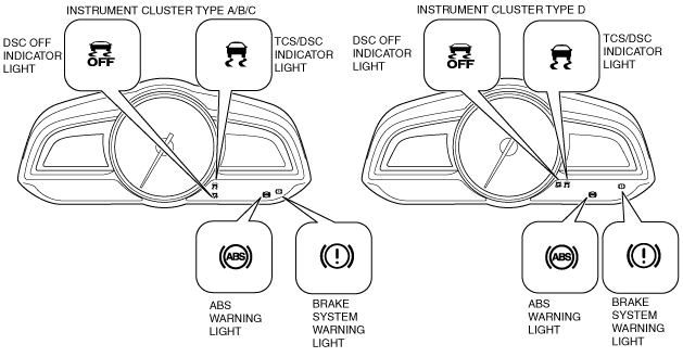
Warning light and indicator light
am3zzn00006210
|
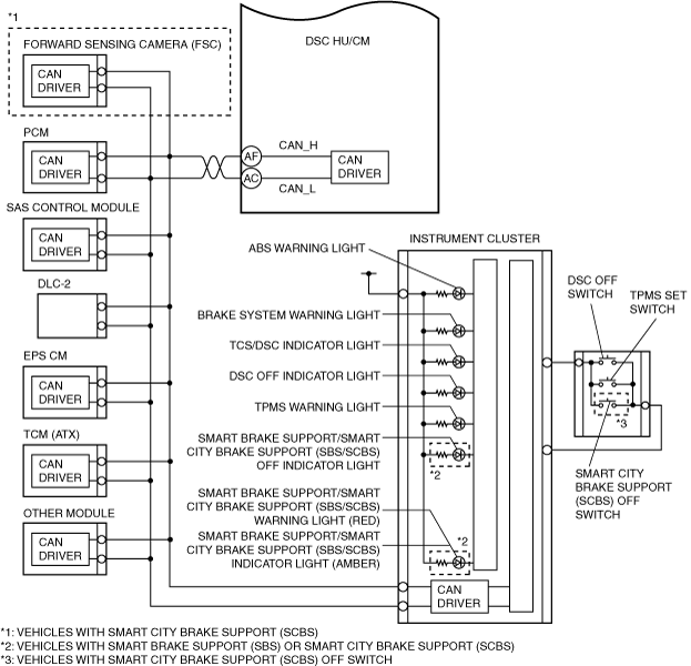
System Wiring Diagram
am3zzw00016154
|
am3zzw00019395
|
Construction
|
Part name |
Function |
|---|---|
|
DSC HU/CM
|
• Makes calculations using input signals from each sensor, controls brake fluid pressure to each wheel, and actuates function (ABS, EBD, TCS, DSC, brake assist control, vehicle roll prevention function*1, hill launch assist (HLA), TPMS*2, and secondary collision reduction (SCR)*3 of the DSC system.
• Outputs the torque reduction request signal, wheel speed signal, and DSC system warning control data via CAN lines.
• Controls the on-board diagnostic system and fail-safe function when there is a malfunction in the DSC system.
|
|
PCM
|
• Controls engine output based on signals from the DSC HU/CM.
• Transmits engine speed, engine torque, brake switch status, and accelerator pedal position data via CAN communication to the DSC HU/CM.
• Transmits gear/shift lever position data via CAN communication to the DSC HU/CM. (MTX)
|
|
TCM (ATX)
|
• Transmits gear/selector lever position data via CAN communication to the DSC HU/CM.
|
|
EPS CM
|
• Transmits steering angle data via CAN communication to the DSC HU/CM.
|
|
SAS control module
|
• Detects the lateral-G (vehicle lateral acceleration speed), the yaw rate (vehicle turning angle speed), and the longitudinal-G (vehicle longitudinal acceleration speed) via CAN communication to the DSC HU/CM.
|
|
Brake system warning light
|
• Notifies the driver that the parking brake is applied.
• Notifies the driver of an ABS or EBD malfunction.
|
|
ABS warning light
|
• Notifies the driver of an ABS malfunction.
|
|
TCS/DSC indicator light
|
• Informs the driver that the TCS is operating (drive wheel is spinning).
• Informs the driver that the DSC is operating (vehicle sideslip occurring).
• Informs the driver of DSC system malfunction.
|
|
DSC OFF switch
|
• Transmits driver intention to release TCS/DSC control to the instrument cluster.
|
|
DSC OFF indicator light
|
• Informs driver that TCS/DSC control has been released due to DSC OFF switch operation.
|
|
TPMS set switch*2
|
• Data initialization after adjusting the tire pressures can be done.
|
|
ABS wheel-speed sensor
|
• Detects the rotation condition of each wheel and transmits it to the DSC HU/CM.
|
|
Brake fluid pressure sensor (Built into DSC HU/CM)
|
• Detects the fluid pressure from the master cylinder.
|