SHIFT AND SELECT MECHANISM [F66M-R]
id0515m5283900
Purpose, Function
• The shift and select mechanism moves the shift fork to change gears according to the operation of the shift lever in the cabin.
Construction
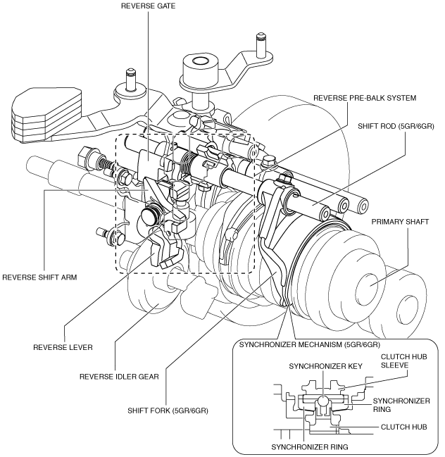
Reverse pre-balk system mechanism
-
• A reverse pre-balk system mechanism, which operates during reverse shifting, and the first selective sliding type reverse idler gear for the SKYACTIVE-MT have been adopted.
• The reverse pre-balk system mechanism operates in conjunction with the reverse shift arm and reverse gate during reverse shifting to shift to the reverse gear by stopping the primary shaft rotation using the shift rod (5GR/6GR), shift fork (5GR/6GR), and synchronizer mechanism (5GR/6GR). Due to this, the synchronizer mechanism of the reverse idler gear has been eliminated.
• The sliding resistance of the synchronizer mechanism has been reduced by eliminating the synchronizer mechanism of the reverse idler gear.
• The reverse idler gear rotation is stopped by the adoption of the selective sliding type reverse idler gear, and the rotational resistance has been reduced.
Operation
-
Note
-
• Shifting operations from neutral to each gear are explained in this section.
1GR
1. When the shift lever in the cabin is tilted to the left to shift to the 1th gear, the shift and select mechanism operates as follows:
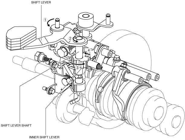
- (1) The select lever moves in the direction of arrow 1 shown in the figure.
- (2) Following the movement of the select lever, the select lever shaft moves in the direction of arrow 2 shown in the figure.
- (3) Following the movement of the select lever shaft, the arm part of the select arm moves in the directions of arrows 3 shown in the figure.
-
- (4) Following the movement of the select arm, the interlock sleeve moves in the direction of arrow 4 shown in the figure.
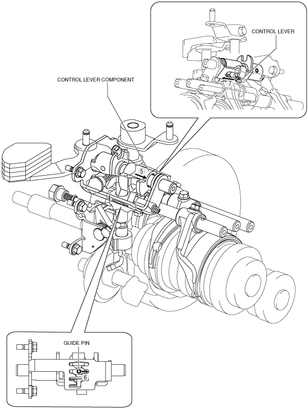
- (5) Following the movement of the interlock sleeve, the control lever component moves in the direction of arrow 5 shown in the figure.
- (6) Following the movement of the control lever component, the guide pin moves in the direction of arrow 6 shown in the figure.
- (7) Following the movement of the control lever component, the control lever moves in the direction of arrow 7 shown in the figure.
2. When the shift lever in the cabin is subsequently tilted forward, the shift and select mechanism operates as follows:
- (1) The shift lever in the engine compartment moves in the direction of arrow 8 shown in the figure.
- (2) Following the movement of the shift lever in the engine compartment, the shift lever shaft moves in the direction of arrow 9 shown in the figure.
- (3) Following the movement of the shift lever shaft, the inner shift lever moves in the direction of arrow 10 shown in the figure.
- (4) Following the movement of the inner shift lever, the lever part of the inner shift lever moves in the direction of arrow 11 shown in the figure.
-
- (5) Following the movement of the lever part of the inner shift lever, the control lever component moves in the direction of arrow 12 shown in the figure.
- (6) Following the movement of the control lever component, the guide pin moves in the direction of arrow 13 shown in the figure.
- (7) Following the movement of the control lever component, the control lever moves in the direction of arrow 14 shown in the figure.
-
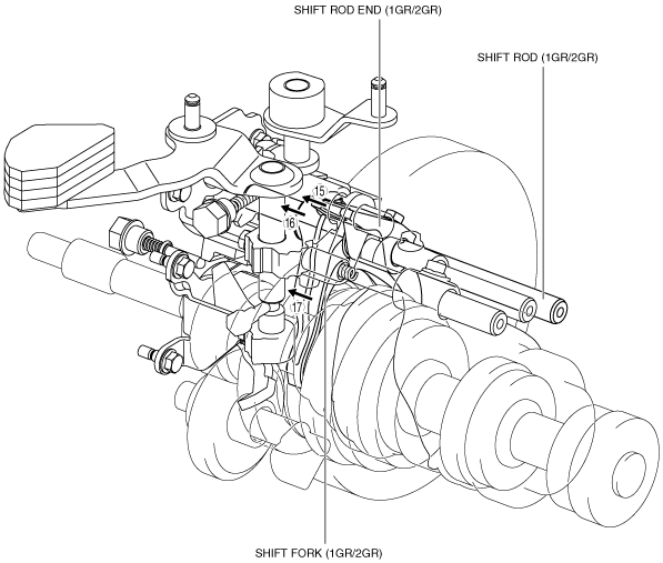
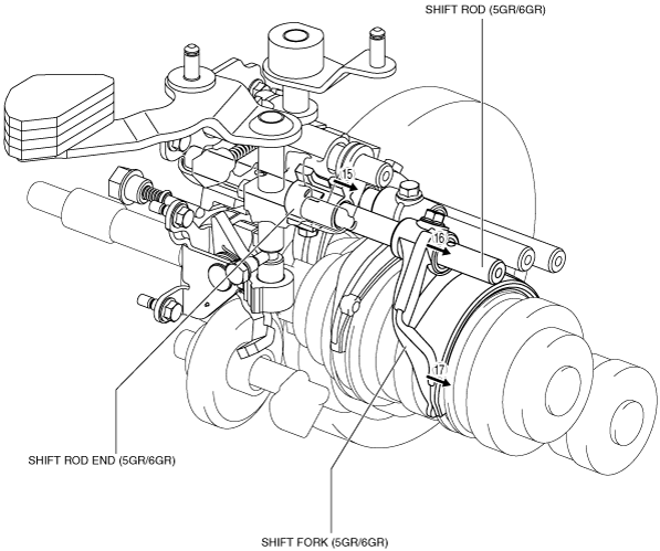
- (8) The control lever pushes the shift rod end and moves it in the direction of arrow 15 shown in the figure.
- (9) The shift rod end and the shift fork are integrated with the shift rod. Therefore, the movement of the shift rod end is transmitted to the shift fork via the shift rod, and the shift fork moves in the direction of arrow 16.
- (10) The shift fork moves the clutch hub sleeve in the direction of arrow 17 shown in the figure.
3. The shift change to 1GR is completed.
2GR
1. When the shift lever in the cabin is tilted to the left to shift to the 2nd gear, the shift and select mechanism operates as follows:
- (1) The select lever moves in the direction of arrow 1 shown in the figure.
- (2) Following the movement of the select lever, the select lever shaft moves in the direction of arrow 2 shown in the figure.
- (3) Following the movement of the select lever shaft, the arm part of the select arm moves in the directions of arrows 3 shown in the figure.
-
- (4) Following the movement of the select arm, the interlock sleeve moves in the direction of arrow 4 shown in the figure.
- (5) Following the movement of the interlock sleeve, the control lever component moves in the direction of arrow 5 shown in the figure.
- (6) Following the movement of the control lever component, the guide pin moves in the direction of arrow 6 shown in the figure.
- (7) Following the movement of the control lever component, the control lever moves in the direction of arrow 7 shown in the figure.
2. When the shift lever in the cabin is subsequently tilted rearward, the shift and select mechanism operates as follows:
- (1) The shift lever in the engine compartment moves in the direction of arrow 8 shown in the figure.
- (2) Following the movement of the shift lever in the engine compartment, the shift lever shaft moves in the direction of arrow 9 shown in the figure.
- (3) Following the movement of the shift lever shaft, the inner shift lever moves in the direction of arrow 10 shown in the figure.
- (4) Following the movement of the inner shift lever, the lever part of the inner shift lever moves in the direction of arrow 11 shown in the figure.
-
- (5) Following the movement of the lever part of the inner shift lever, the control lever component moves in the direction of arrow 12 shown in the figure.
- (6) Following the movement of the control lever component, the guide pin moves in the direction of arrow 13 shown in the figure.
- (7) Following the movement of the control lever component, the control lever moves in the direction of arrow 14 shown in the figure.
-
- (8) The control lever pushes the shift rod end and moves it in the direction of arrow 15 shown in the figure.
- (9) The shift rod end and the shift fork are integrated with the shift rod. Therefore, the movement of the shift rod end is transmitted to the shift fork via the shift rod, and the shift fork moves in the direction of arrow 16.
- (10) The shift fork moves the clutch hub sleeve in the direction of arrow 17 shown in the figure.
3. The shift change to 2GR is completed.
3GR
1. When the shift lever in the cabin is tilted forward to shift to the 3rd gear, the shift and select mechanism operates as follows:
- (1) The shift lever in the engine compartment moves in the direction of arrow 1 shown in the figure.
- (2) Following the movement of the shift lever in the engine compartment, the shift lever shaft moves in the direction of arrow 2 shown in the figure.
- (3) Following the movement of the shift lever shaft, the inner shift lever moves in the direction of arrow 3 shown in the figure.
- (4) Following the movement of the inner shift lever, the lever part of the inner shift lever moves in the direction of arrow 4 shown in the figure.
-
- (5) Following the movement of the lever part of the inner shift lever, the control lever component moves in the direction of arrow 5 shown in the figure.
- (6) Following the movement of the control lever component, the guide pin moves in the direction of arrow 6 shown in the figure.
- (7) Following the movement of the control lever component, the control lever moves in the direction of arrow 7 shown in the figure.
-
- (8) The control lever pushes the shift rod end and moves it in the direction of arrow 8 shown in the figure.
- (9) The shift rod end and the shift fork are integrated with the shift rod. Therefore, the movement of the shift rod end is transmitted to the shift fork via the shift rod, and the shift fork moves in the direction of arrow 9.
- (10) The shift fork moves the clutch hub sleeve in the direction of arrow 10 shown in the figure.
2. The shift change to 3GR is completed.
4GR
1. When the shift lever in the cabin is tilted rearward to shift to the 4th gear, the shift and select mechanism operates as follows:
- (1) The shift lever in the engine compartment moves in the direction of arrow 1 shown in the figure.
- (2) Following the movement of the shift lever in the engine compartment, the shift lever shaft moves in the direction of arrow 2 shown in the figure.
- (3) Following the movement of the shift lever shaft, the inner shift lever moves in the direction of arrow 3 shown in the figure.
- (4) Following the movement of the inner shift lever, the lever part of the inner shift lever moves in the direction of arrow 4 shown in the figure.
-
- (5) Following the movement of the lever part of the inner shift lever, the control lever component moves in the direction of arrow 5 shown in the figure.
- (6) Following the movement of the control lever component, the guide pin moves in the direction of arrow 6 shown in the figure.
- (7) Following the movement of the control lever component, the control lever moves in the direction of arrow 7 shown in the figure.
-
- (8) The control lever pushes the shift rod end and moves it in the direction of arrow 8 shown in the figure.
- (9) The shift rod end and the shift fork are integrated with the shift rod. Therefore, the movement of the shift rod end is transmitted to the shift fork via the shift rod, and the shift fork moves in the direction of arrow 9.
- (10) The shift fork moves the clutch hub sleeve in the direction of arrow 10 shown in the figure.
2. The shift change to 4GR is completed.
5GR
1. When the shift lever in the cabin is tilted to the right to shift to the 5th gear, the shift and select mechanism operates as follows:
- (1) The select lever moves in the direction of arrow 1 shown in the figure.
- (2) Following the movement of the select lever, the select lever shaft moves in the direction of arrow 2 shown in the figure.
- (3) Following the movement of the select lever shaft, the arm part of the select arm moves in the directions of arrows 3 shown in the figure.
-
- (4) Following the movement of the select arm, the interlock sleeve moves in the direction of arrow 4 shown in the figure.
- (5) Following the movement of the interlock sleeve, the control lever component moves in the direction of arrow 5 shown in the figure.
- (6) Following the movement of the control lever component, the guide pin moves in the direction of arrow 6 shown in the figure.
- (7) Following the movement of the control lever component, the control lever moves in the direction of arrow 7 shown in the figure.
2. When the shift lever in the cabin is subsequently tilted forward, the shift and select mechanism operates as follows:
- (1) The shift lever in the engine compartment moves in the direction of arrow 8 shown in the figure.
- (2) Following the movement of the shift lever in the engine compartment, the shift lever shaft moves in the direction of arrow 9 shown in the figure.
- (3) Following the movement of the shift lever shaft, the inner shift lever moves in the direction of arrow 10 shown in the figure.
- (4) Following the movement of the inner shift lever, the lever part of the inner shift lever move in the direction of arrow 11 shown in the figure.
-
- (5) Following the movement of the lever part of the inner shift lever, the control lever component moves in the direction of arrow 12 shown in the figure.
- (6) Following the movement of the control lever component, the guide pin moves in the direction of arrow 13 shown in the figure.
- (7) Following the movement of the control lever component, the control lever moves in the direction of arrow 14 shown in the figure.
-
- (8) The control lever pushes the shift rod end and moves it in the direction of arrow 15 shown in the figure.
- (9) The shift rod end and the shift fork are integrated with the shift rod. Therefore, the movement of the shift rod end is transmitted to the shift fork via the shift rod, and the shift fork moves in the direction of arrow 16.
- (10) The shift fork moves the clutch hub sleeve in the direction of arrow 17 shown in the figure.
3. The shift change to 5GR is completed.
6GR
1. When the shift lever in the cabin is tilted to the right to shift to the 6th gear, the shift and select mechanism operates as follows:
- (1) The select lever moves in the direction of arrow 1 shown in the figure.
- (2) Following the movement of the select lever, the select lever shaft moves in the direction of arrow 2 shown in the figure.
- (3) Following the movement of the select lever shaft, the arm part of the select arm moves in the directions of arrows 3 shown in the figure.
-
- (4) Following the movement of the select arm, the interlock sleeve moves in the direction of arrow 4 shown in the figure.
- (5) Following the movement of the interlock sleeve, the control lever component moves in the direction of arrow 5 shown in the figure.
- (6) Following the movement of the control lever component, the guide pin moves in the direction of arrow 6 shown in the figure.
- (7) Following the movement of the control lever component, the control lever moves in the direction of arrow 7 shown in the figure.
2. When the shift lever in the cabin is subsequently tilted rearward, the shift and select mechanism operates as follows:
- (1) The shift lever in the engine compartment moves in the direction of arrow 8 shown in the figure.
- (2) Following the movement of the shift lever in the engine compartment, the shift lever shaft moves in the direction of arrow 9 shown in the figure.
- (3) Following the movement of the shift lever shaft, the inner shift lever moves in the direction of arrow 10 shown in the figure.
- (4) Following the movement of the inner shift lever, the lever part of the inner shift lever moves in the direction of arrow 11 shown in the figure.
-
- (5) Following the movement of the lever part of the inner shift lever, the control lever component moves in the direction of arrow 12 shown in the figure.
- (6) Following the movement of the control lever component, the guide pin moves in the direction of arrow 13 shown in the figure.
- (7) Following the movement of the control lever component, the control lever moves in the direction of arrow 14 shown in the figure.
-
- (8) The control lever pushes the shift rod end and moves it in the direction of arrow 15 shown in the figure.
- (9) The shift rod end and the shift fork are integrated with the shift rod. Therefore, the movement of the shift rod end is transmitted to the shift fork via the shift rod, and the shift fork moves in the direction of arrow 16.
- (10) The shift fork moves the clutch hub sleeve in the direction of arrow 17 shown in the figure.
3. The shift change to 6GR is completed.
Reverse
-
Note
-
• If the shift lever operation is cancelled during shifting operation, shift back to neutral, depress the clutch pedal again, and operate the shift lever again. If the lever operation is performed again from the interrupted state, a gear-grinding sound may be heard.
1. When the shift lever in the cabin is pressed in and tilted to the left to shift to the reverse gear, the shift and select mechanism operates as follows:
- (1) The select lever moves in the direction of arrow 1 shown in the figure.
- (2) Following the movement of the select lever, the select lever shaft moves in the direction of arrow 2 shown in the figure.
- (3) Following the movement of the select lever shaft, the arm part of the select arm moves in the directions of arrows 3 shown in the figure.
-
- (4) Following the movement of the select arm, the interlock sleeve moves in the direction of arrow 4 shown in the figure.
- (5) Following the movement of the interlock sleeve, the lever part of the interlock sleeve moves in the direction of arrow 5 shown in the figure.
- (6) Following the movement of the lever part of the interlock sleeve, the reverse gate moves in the direction of arrow 6 shown in the figure.
- (7) Following the movement of the interlock sleeve, the control lever component moves in the direction of arrow 7 shown in the figure.
-
- (8) Following the movement of the control lever component, the guide pin moves in the direction of arrow 8 shown in the figure.
- (9) Following the movement of the control lever component, the control lever moves in the direction of arrow 9 shown in the figure.
2. When the shift lever in the cabin is subsequently tilted forward, the shift and select mechanism operates as follows:
- (1) The shift lever in the engine compartment moves in the direction of arrow 10 shown in the figure.
- (2) Following the movement of the shift lever in the engine compartment, the shift lever shaft moves in the direction of arrow 11 shown in the figure.
- (3) Following the movement of the shift lever shaft, the inner shift lever moves in the direction of arrow 12 shown in the figure.
- (4) Following the movement of the inner shift lever, the lever part of the inner shift lever moves in the direction of arrow 13 shown in the figure.
-
- (5) Following the movement of the lever part of the inner shift lever, the control lever component moves in the direction of arrow 14 shown in the figure.
- (6) Following the movement of the control lever component, the guide pin moves in the direction of arrow 15 shown in the figure.
- (7) Following the movement of the control lever component, the control lever moves in the direction of arrow 16 shown in the figure.
-
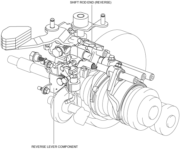
- (8) The control lever pushes the shift rod end and moves it in the direction of arrow 17 shown in the figure.
- (9) The shift rod end pushes the reverse lever component and moves it in the direction of arrow 18 shown in the figure.
-
- (10) The reverse lever of the reverse lever component pushes the reverse shift arm and moves it in the direction of arrow 19 shown in the figure.
- (11) The reverse shift arm pushes the reverse gate and moves it in the direction of arrow 20 shown in the figure.
- (12) The reverse gate and shift fork (5GR/6GR) are integrated with the shift rod. Therefore, the movement of the shift rod end is transmitted to the shift fork via the shift rod, and the shift fork moves in the direction of arrows 21 to stop the primary shaft rotation.
- (13) The reverse lever pushes the reverse idler gear and moves it in the direction of arrow 22 shown in the figure.
3. The shift change to the reverse gear is completed.