ac5wzw00002839
|
MANUAL TRANSAXLE REMOVAL/INSTALLATION [C66M-R (SKYACTIV-G 2.0, SKYACTIV-G 2.5)]
id0515m81600j1
Removal
1. Disconnect the negative battery cable. (See NEGATIVE BATTERY CABLE DISCONNECTION/CONNECTION [SKYACTIV-G 1.5, SKYACTIV-G 2.0, SKYACTIV-G 2.5].)
2. Remove the plug hole plate. (See PLUG HOLE PLATE REMOVAL/INSTALLATION [SKYACTIV-G 1.5, SKYACTIV-G 2.0, SKYACTIV-G 2.5].)
3. Remove the front under cover No.2. (See FRONT UNDER COVER No.2 REMOVAL/INSTALLATION.)
4. Remove the front under cover No.1. (See FRONT UNDER COVER No.1 REMOVAL/INSTALLATION.)
5. Remove the splash shield. (See SPLASH SHIELD REMOVAL/INSTALLATION.)
6. Drain the manual transaxle oil. (See MANUAL TRANSAXLE OIL REPLACEMENT [C66M-R].)
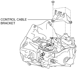
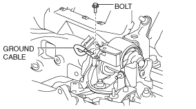
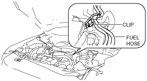
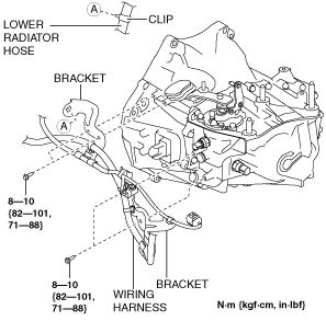
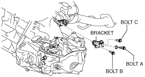
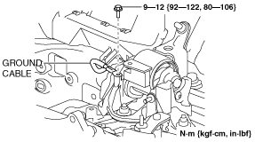
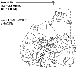
7. Disconnect and/or remove the following parts in the engine compartment.
ac5wzw00002839
|
am3zzw00017341
|
am6zzw00008393
|
ac5wzw00002841
|
8. Disconnect and/or remove the following parts related to the suspension and axle.
9. Disconnect and/or remove the following parts from the underside of the vehicle.
SKYACTIV-G 2.0 (No.1 engine mount type A), SKYACTIV-G 2.5
am3zzw00019175
|
SKYACTIV-G 2.0 (No.1 engine mount type B)
am3zzw00020129
|
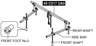
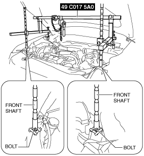
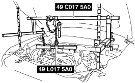
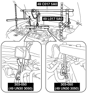
10. Install the SST (49 C017 5A0, 49 UN30 3050, 49 L017 5A0) using the following procedure.
am3zzw00019176
|
am6zzw00010817
|
am6zzw00010818
|
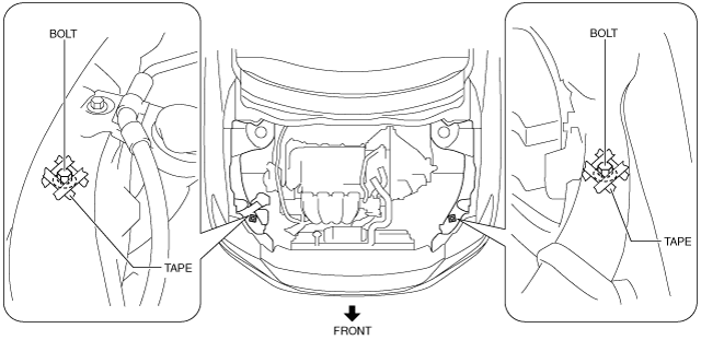
Engine front side
am6zzw00010819
|
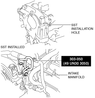
Engine rear side
am6zzw00010820
|
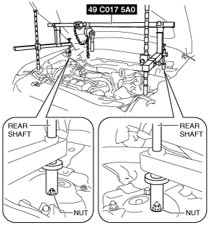
am6zzw00008396
|
am6zzw00008397
|
am6zzw00008398
|
am6zzw00008399
|
am6zzw00008400
|
11. Remove in the order indicated in the table.
am3zzw00019177
|
|
1
|
Transaxle mounting bolt (upper side)
|
|
2
|
No.4 engine mount bracket
|
|
3
|
Transaxle mounting bolt (lower side)
|
|
4
|
MTX
|
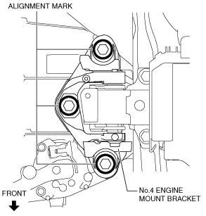
No.4 engine mount bracket removal note
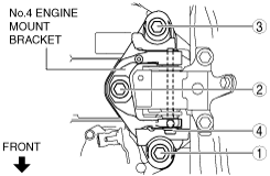
1. Place alignment marks on the locations shown in the figure so that they can be assembled to the same positions as before removal.
am3zzw00019178
|
2. Remove the No.4 engine mount bracket.
Transaxle mounting bolt removal note
1. Adjust the SST (49 C017 5A0) and lean the engine toward the MTX.
am6zzw00008399
|
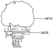
2. Support the MTX on a jack.
am6zzw00008402
|
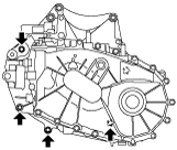
3. Remove the transaxle mounting bolts (lower side).
ac5uuw00000745
|
4. Remove the MTX.
Installation
1. Set the MTX on a jack and lift into place.
am6zzw00008402
|
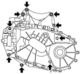
2. Install the MTX to the engine, and tighten the transaxle mounting bolts.
am3uuw00008227
|
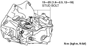
3. Tighten the stud bolts for the MTX.
ac5wzw00002845
|
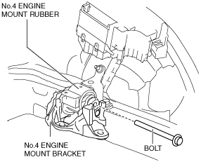
4. Install the No.4 engine mount bracket to No.4 engine mount rubber, and temporarily tighten the installation bolt.
am3zzw00019179
|
5. Lift up the MTX using the SSTs (49 C017 5A0, 49 L017 5A0), pass the MTX stud bolts through the No.4 engine mount bracket, and temporarily tighten the No.4 engine mount installation nuts.
am3zzw00019180
|
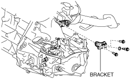
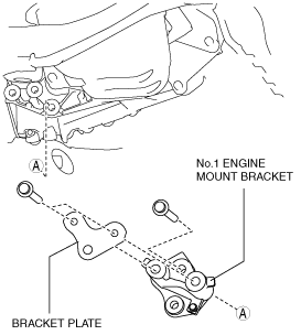
6. Install the No.1 engine mount bracket and bracket plate to the MTX, and temporarily tighten the installation bolts.
SKYACTIV-G 2.0 (No.1 engine mount type A), SKYACTIV-G 2.5
am3zzw00019175
|
SKYACTIV-G 2.0 (No.1 engine mount type B)
am3zzw00020129
|
7. Install the front crossmember component and No.1 engine mount rubber as a single unit. (See FRONT CROSSMEMBER REMOVAL/INSTALLATION [SKYACTIV-G 1.5, SKYACTIV-G 2.0, SKYACTIV-G 2.5].)
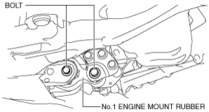
8. Temporarily tighten the No.1 engine mount rubber installation bolts.
SKYACTIV-G 2.0 (No.1 engine mount type A), SKYACTIV-G 2.5
am3zzw00019181
|
SKYACTIV-G 2.0 (No.1 engine mount type B)
am3zzw00020130
|
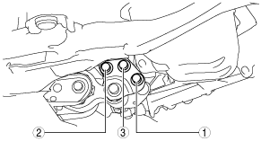
9. Align the positions of the No.4 engine mount bracket installation nuts with the No.4 engine mount bracket.
am3zzw00014236
|
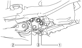
10. Tighten the No.4 engine mount bracket installation nuts and bolt in the order shown in the figure.
am3zzw00019182
|
|
No. |
Tightening torque |
|---|---|
|
1, 2, 3
|
92—116 N·m {9.4—11 kgf·m, 68—85 ft·lbf}
|
|
4
|
81—99 N·m {8.3—10 kgf·m, 60—73 ft·lbf}
|
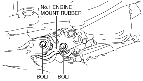
11. Tighten the No.1 engine mount bracket and bracket plate installation bolts in the order shown in the figure.
SKYACTIV-G 2.0 (No.1 engine mount type A), SKYACTIV-G 2.5
am3uuw00010679
|
SKYACTIV-G 2.0 (No.1 engine mount type B)
am3zzw00016024
|
12. Remove the SSTs (49 C017 5A0, 49 L017 5A0).
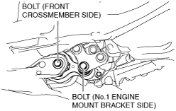
13. Tighten the No.1 engine mount rubber installation bolts.
SKYACTIV-G 2.0 (No.1 engine mount type A), SKYACTIV-G 2.5
am3zzw00020974
|
Tightening torque
|
Installation position |
Tightening torque |
|---|---|
|
No.1 engine mount bracket side
|
130—151 N·m {14—15 kgf·m, 96—111 ft·lbf}
|
|
Front crossmember side
|
130—164 N·m {14—16 kgf·m, 96—120 ft·lbf}
|
SKYACTIV-G 2.0 (No.1 engine mount type B)
am3zzw00020131
|
Tightening torque
|
Installation position |
Tightening torque |
|---|---|
|
No.1 engine mount bracket side
|
140—163 N·m {15—16 kgf·m, 104—120 ft·lbf}
|
|
Front crossmember side
|
130—164 N·m {14—16 kgf·m, 96—120 ft·lbf}
|
14. Connect and/or Install the following parts to the underside of the vehicle.
15. Connect and/or Install the following parts related to the suspension and axle.
16. Connect and/or install the following parts in the engine compartment.
am6zzw00008398
|
am6zzw00010818
|
ac5wzw00002846
|
am6zzw00008406
|
am3zzw00016026
|
ac5wzw00002847
|
17. Install the splash shield. (See SPLASH SHIELD REMOVAL/INSTALLATION.)
18. Install the front under cover No.1. (See FRONT UNDER COVER No.1 REMOVAL/INSTALLATION.)
19. Add the specified amount of specified manual transaxle oil. (See MANUAL TRANSAXLE OIL REPLACEMENT [C66M-R].)
20. Install the front under cover No.2. (See FRONT UNDER COVER No.2 REMOVAL/INSTALLATION.)
21. Connect the negative battery cable. (See NEGATIVE BATTERY CABLE DISCONNECTION/CONNECTION [SKYACTIV-G 1.5, SKYACTIV-G 2.0, SKYACTIV-G 2.5].)
22. Install the plug hole plate. (See PLUG HOLE PLATE REMOVAL/INSTALLATION [SKYACTIV-G 1.5, SKYACTIV-G 2.0, SKYACTIV-G 2.5].)
23. If the MTX is overhauled, perform the “INSPECTION AFTER MANUAL TRANSAXLE OVERHAUL”. (See INSPECTION AFTER MANUAL TRANSAXLE OVERHAUL [C66M-R].)