DTC U3003:16, U3003:17 [CLIMATE CONTROL UNIT (FULL-AUTO AIR CONDITIONER)]


id0702k2731000


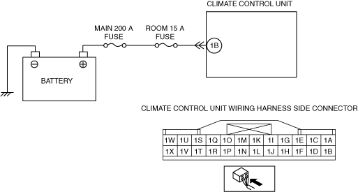
With Dual Type Climate Control Unit

System malfunction location

•  U3003:16: Climate control unit power supply circuit voltage below threshold (9.98 V or less)
•  U3003:17: Climate control unit power supply circuit voltage above threshold (16.21 V or more)
Detection condition
•  Climate control unit power supply voltage is other than 9.99—16.20 V
Fail-safe function
Not applicable
Possible cause
•  Generator system malfunction
•  ROOM 15 A fuse malfunction
•  Battery malfunction
•  Climate control unit connector malfunction
•  Open circuit in wiring harness between the followings:
―  Climate control unit terminal 1B—battery positive terminal
•  Short to ground in wiring harness between the following terminal and ROOM 15 A fuse:
―  Climate control unit terminal 1B
•  Climate control unit malfunction


Diagnostic Procedure

STEP

INSPECTION

ACTION

1
INSPECT PCM DTC (INSPECT GENERATOR CIRCUIT)
•  Switch the ignition off.
•  Connect the M-MDS to the DLC-2.
•  Are any DTCs present?
Yes
Go to the applicable DTC inspection.
No
Go to the next step.
2
INSPECT FUSE
•  Switch the ignition off.
•  Remove the ROOM 15 A fuse.
•  Is the fuse normal?
Yes
Install the ROOM 15 A fuse, then go to the next step.
No
If the fuse is blown:
•  Refer to the wiring diagram and verify whether or not there is a common connector between ROOM 15 A fuse and climate control unit terminal.
If there is a common connector:
―  Determine the malfunctioning part by inspecting the common connector and the terminal for corrosion, damage, or pin disconnection, and the common wiring harness for a short to ground.
―  Repair or replace the malfunctioning part.
If there is no common connector:
―  Repair or replace the wiring harness which has a short to ground.
•  Replace the fuse.
If the fuse is damaged:
•  Replace the fuse.
Then go to Step 6.
3
INSPECT BATTERY
•  Is the battery normal?
Yes
Go to the next step.
No
Replace or charge the battery.
Then go to Step 6.
4
VERIFY CLIMATE CONTROL UNIT CONNECTOR CONDITION
•  Disconnect the climate control unit connector.
•  Inspect the connector and terminals (corrosion, damage, pin disconnection).
•  Are the connector and terminals normal?
Yes
Go to the next step.
No
Repair/replace the connector or terminal.
After repair procedure, go to Step 6.
5
INSPECT CLIMATE CONTROL UNIT POWER SUPPLY CIRCUIT FOR OPEN CIRCUIT
•  Inspect for continuity between the following terminals (wiring harness-side) and battery positive terminal.
―  Climate control unit terminal 1B
•  Is there continuity?
Yes
Go to the next step.
No
Refer to the wiring diagram and verify whether or not there is a common connector between climate control unit terminal and battery positive terminal.
If there is a common connector:
•  Determine the malfunctioning part by inspecting the common connector and the terminal for corrosion, damage, or pin disconnection, and the common wiring harness for an open circuit.
•  Repair or replace the malfunctioning part.
If there is no common connector:
•  Repair or replace the wiring harness which has an open circuit.
Go to the next step.
6
VERIFY THAT SAME DTC IS NOT OUTPUT AGAIN
•  Reconnect the disconnected connectors.
•  Clear the DTC from the climate control unit memory using the M-MDS.
•  Perform the DTC inspection for the climate control unit using the M-MDS.
•  Is the same DTC displayed?
Yes
Repeat the inspection from Step 1.
•  If the malfunction recurs, replace the climate control unit.
Go to the next step.
No
Go to the next step.
7
VERIFY THAT NO OTHER DTCs ARE PRESENT
•  Verify other DTCs displayed.
•  Are any other DTCs displayed?
Yes
Repair or replace the malfunctioning part according to the applicable DTC troubleshooting.
No
DTC troubleshooting completed.


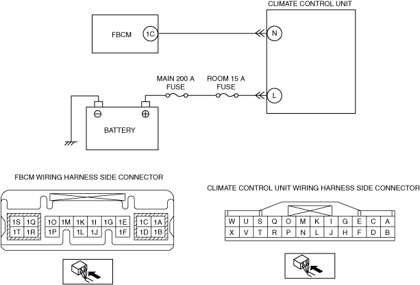
With Single Type Climate Control Unit

System malfunction location

•  U3003:16: Climate control unit power supply circuit voltage below threshold (10.00 V or less)
•  U3003:17: Climate control unit power supply circuit voltage above threshold (17.30 V or more)
Detection condition
•  Climate control unit power supply voltage is other than 10.00—17.29 V
Fail-safe function
Not applicable
Possible cause
•  Generator system malfunction
•  ROOM 15 A fuse malfunction
•  Battery malfunction
•  Climate control unit connector malfunction
•  Open circuit in wiring harness between the following terminals:
―  Climate control unit terminal L—battery positive terminal
•  Short to ground in wiring harness between the following terminal and ROOM 15 A fuse:
―  Climate control unit terminal L
•  Open circuit in wiring harness between the following terminals:
―  Climate control unit terminal N—front body control module (FBCM) terminal 1C
•  Short to ground in wiring harness between the following terminals:
―  Climate control unit terminal N—front body control module (FBCM) terminal 1C
•  Climate control unit malfunction


Diagnostic Procedure

STEP

INSPECTION

ACTION

1
INSPECT PCM DTC (INSPECT GENERATOR CIRCUIT)
•  Switch the ignition off.
•  Connect the M-MDS to the DLC-2.
•  Are any DTCs present?
Yes
Go to the applicable DTC inspection.
No
Go to the next step.
2
INSPECT FUSE
•  Switch the ignition off.
•  Remove the ROOM 15 A fuse.
•  Is the fuse normal?
Yes
Install the ROOM 15 A fuse, then go to the next step.
No
If the fuse is blown:
•  Refer to the wiring diagram and verify whether or not there is a common connector between ROOM 15 A fuse and climate control unit terminal.
If there is a common connector:
―  Determine the malfunctioning part by inspecting the common connector and the terminal for corrosion, damage, or pin disconnection, and the common wiring harness for a short to ground.
―  Repair or replace the malfunctioning part.
If there is no common connector:
―  Repair or replace the wiring harness which has a short to ground.
•  Replace the fuse.
If the fuse is damaged:
•  Replace the fuse.
Then go to Step 8.
3
INSPECT BATTERY
•  Is the battery normal?
Yes
Go to the next step.
No
Replace or charge the battery.
Then go to Step 8.
4
VERIFY CLIMATE CONTROL UNIT CONNECTOR CONDITION
•  Disconnect the climate control unit connector.
•  Inspect the connector and terminals (corrosion, damage, pin disconnection).
•  Are the connector and terminals normal?
Yes
Go to the next step.
No
Repair/replace the connector or terminal.
After repair procedure, go to the Step 8.
5
INSPECT CLIMATE CONTROL UNIT POWER SUPPLY CIRCUIT FOR OPEN CIRCUIT
•  Inspect for continuity between the following terminals (wiring harness-side) and battery positive terminal:
―  Climate control unit terminal L
•  Is there continuity?
Yes
Go to the next step.
No
Refer to the wiring diagram and verify whether or not there is a common connector between climate control unit terminal and battery positive terminal.
If there is a common connector:
•  Determine the malfunctioning part by inspecting the common connector and the terminal for corrosion, damage, or pin disconnection, and the common wiring harness for an open circuit.
•  Repair or replace the malfunctioning part.
If there is no common connector:
•  Repair or replace the wiring harness which has an open circuit.
Go to Step 8.
6
INSPECT CLIMATE CONTROL UNIT POWER SUPPLY CIRCUIT FOR SHORT TO GROUND
•  Inspect for continuity between the following terminals (wiring harness-side) and body ground:
―  Climate control unit terminal N
•  Is there continuity?
Yes
Refer to the wiring diagram and verify whether or not there is a common connector between climate control unit terminal and front body control module (FBCM) terminal.
If there is a common connector:
•  Determine the malfunctioning part by inspecting the common connector and the terminal for corrosion, damage, or pin disconnection, and the common wiring harness for a short to ground.
•  Repair or replace the malfunctioning part.
If there is no common connector:
•  Repair or replace the wiring harness which has a short to ground.
Go to Step 8.
No
Go to the next step.
7
INSPECT CLIMATE CONTROL UNIT POWER SUPPLY CIRCUIT FOR OPEN CIRCUIT
•  Inspect for continuity between the following terminals (wiring harness-side):
―  Climate control unit terminal N—front body control module (FBCM) terminal 1C
•  Is there continuity?
Yes
Go to the next step.
No
Refer to the wiring diagram and verify whether or not there is a common connector between climate control unit terminal and front body control module (FBCM) terminal.
If there is a common connector:
•  Determine the malfunctioning part by inspecting the common connector and the terminal for corrosion, damage, or pin disconnection, and the common wiring harness for an open circuit.
•  Repair or replace the malfunctioning part.
If there is no common connector:
•  Repair or replace the wiring harness which has an open circuit.
Go to the next step.
8
VERIFY THAT SAME DTC IS NOT OUTPUT AGAIN
•  Reconnect the disconnected connectors.
•  Clear the DTC from the climate control unit memory using the M-MDS.
•  Perform the DTC inspection for the climate control unit using the M-MDS.
•  Is the same DTC displayed?
Yes
Repeat the inspection from Step 1.
•  If the malfunction recurs, replace the climate control unit.
Go to the next step.
No
Go to the next step.
9
VERIFY THAT NO OTHER DTCs ARE PRESENT
•  Verify other DTCs displayed.
•  Are any other DTCs displayed?
Yes
Repair or replace the malfunctioning part according to the applicable DTC troubleshooting.
No
DTC troubleshooting completed.