|
am3zzw00019888
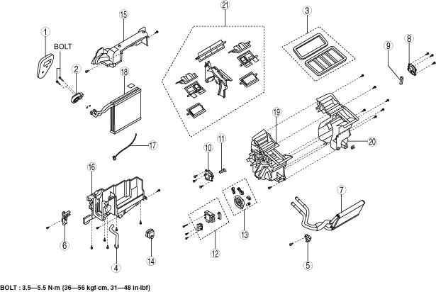
A/C UNIT DISASSEMBLY/ASSEMBLY
id071100800300
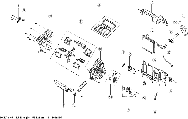
Full-auto Air Conditioner (L.H.D. (Without 27 Screws))
1. Disassemble in the order indicated in the table.
am3zzw00019888
|
|
Step |
Part name |
Disassembly/assembly of main parts |
||
|---|---|---|---|---|
|
Heater core |
Evaporator temperature sensor |
Evaporator |
||
|
1
|
Polyurethane foam
|
X
|
X
|
X
|
|
2
|
Expansion valve
|
-
|
-
|
X
|
|
3
|
Adhesive polyurethane
|
-
|
-
|
-
|
|
4
|
Drain hose
|
-
|
-
|
-
|
|
5
|
Plate A
|
X
|
X
|
X
|
|
6
|
Plate B
|
X
|
X
|
X
|
|
7
|
Heater core
|
X
|
X
|
X
|
|
8
|
Driver-side air mix actuator (with dual type climate control unit)
|
-
|
-
|
-
|
|
9
|
Driver-side air mix link (with dual type climate control unit)
|
-
|
-
|
-
|
|
10
|
Passenger-side air mix actuator (with dual type climate control unit)
|
-
|
-
|
-
|
|
Air mix actuator (with single type climate control unit)
|
||||
|
11
|
Passenger-side air mix link (with dual type climate control unit)
|
-
|
-
|
-
|
|
Air mix link (with single type climate control unit)
|
||||
|
12
|
Airflow mode actuator
|
-
|
-
|
-
|
|
13
|
Airflow mode link set
|
-
|
-
|
-
|
|
14
|
PTC heater (with PTC heater)
|
-
|
-
|
-
|
|
15
|
Blower fan controller
|
-
|
-
|
-
|
|
16
|
A/C case A
|
-
|
X
|
X
|
|
17
|
A/C case B
|
-
|
X
|
X
|
|
18
|
Evaporator temperature sensor (See Evaporator temperature sensor assembly note.)
|
-
|
X
|
X
|
|
19
|
Evaporator
|
-
|
-
|
X
|
|
20
|
A/C case C
|
-
|
-
|
-
|
|
21
|
A/C case D
|
-
|
-
|
-
|
|
22
|
Door damper
|
-
|
-
|
-
|
2. Assemble in the reverse order of disassembly.
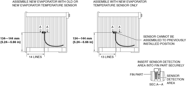
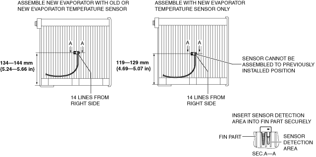
Evaporator temperature sensor assembly note
1. Assemble the evaporator temperature sensor as shown in the figure.
am3zzw00019905
|
Full-auto Air Conditioner (L.H.D. (With 27 Screws))
1. Disassemble in the order indicated in the table.
am3zzw00019906
|
|
Step |
Part name |
Disassembly/assembly of main parts |
||
|---|---|---|---|---|
|
Heater core |
Evaporator temperature sensor |
Evaporator |
||
|
1
|
Polyurethane foam
|
X
|
X
|
X
|
|
2
|
Expansion valve
|
-
|
-
|
X
|
|
3
|
Adhesive polyurethane
|
-
|
-
|
-
|
|
4
|
Drain hose
|
-
|
-
|
-
|
|
5
|
Plate A
|
X
|
X
|
X
|
|
6
|
Plate B
|
X
|
X
|
X
|
|
7
|
Heater core
|
X
|
X
|
X
|
|
8
|
Driver-side air mix actuator (with dual type climate control unit)
|
-
|
-
|
-
|
|
9
|
Driver-side air mix link (with dual type climate control unit)
|
-
|
-
|
-
|
|
10
|
Passenger-side air mix actuator (with dual type climate control unit)
|
-
|
-
|
-
|
|
Air mix actuator (with single type climate control unit)
|
||||
|
11
|
Passenger-side air mix link (with dual type climate control unit)
|
-
|
-
|
-
|
|
Air mix link (with single type climate control unit)
|
||||
|
12
|
Airflow mode actuator
|
-
|
-
|
-
|
|
13
|
Airflow mode link set
|
-
|
-
|
-
|
|
14
|
Blower fan controller
|
-
|
-
|
-
|
|
15
|
A/C case A
|
-
|
X
|
X
|
|
16
|
A/C case B
|
-
|
X
|
X
|
|
17
|
Evaporator temperature sensor (See Evaporator temperature sensor assembly note.)
|
-
|
X
|
X
|
|
18
|
Evaporator
|
-
|
-
|
X
|
|
19
|
A/C case C
|
-
|
-
|
-
|
|
20
|
A/C case D
|
-
|
-
|
-
|
|
21
|
Door damper
|
-
|
-
|
-
|
2. Assemble in the reverse order of disassembly.
Evaporator temperature sensor assembly note
1. Assemble the evaporator temperature sensor as shown in the figure.
am3zzw00019905
|
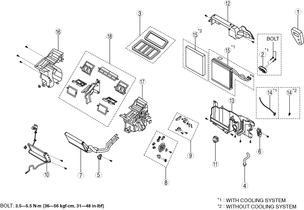
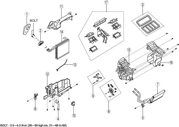
Manual Air Conditioner (L.H.D. (Without 23 Screws))
1. Disassemble in the order indicated in the table.
am3zzw00019883
|
|
Step |
Part name |
Disassembly/assembly of main parts |
||
|---|---|---|---|---|
|
Heater core |
Evaporator temperature sensor |
Evaporator |
||
|
1
|
Polyurethane foam
|
X
|
X
|
X
|
|
2
|
Expansion valve
|
-
|
-
|
X
|
|
3
|
Adhesive polyurethane
|
-
|
-
|
-
|
|
4
|
Drain hose
|
-
|
-
|
-
|
|
5
|
Plate A
|
X
|
X
|
X
|
|
6
|
Plate B
|
X
|
X
|
X
|
|
7
|
Heater core
|
X
|
X
|
X
|
|
8
|
Airflow mode link set
|
X (wire clamp)
|
-
|
-
|
|
9
|
Air mix link
|
-
|
-
|
-
|
|
10
|
PTC heater (with PTC heater)
|
-
|
-
|
-
|
|
11
|
Blower fan controller
|
-
|
-
|
-
|
|
12
|
A/C case A
|
-
|
X
|
X
|
|
13
|
A/C case B
|
-
|
X
|
X
|
|
14
|
Evaporator temperature sensor (See Evaporator temperature sensor assembly note.)
|
-
|
X
|
X
|
|
15
|
Evaporator (with cooling system)
|
-
|
-
|
X
|
|
Case (without cooling system)
|
-
|
-
|
-
|
|
|
16
|
A/C case C
|
-
|
-
|
-
|
|
17
|
A/C case D
|
-
|
-
|
-
|
|
18
|
Door damper
|
-
|
-
|
-
|
2. Assemble in the reverse order of disassembly.
Evaporator temperature sensor assembly note
1. Assemble the evaporator temperature sensor as shown in the figure.
am3zzw00019905
|
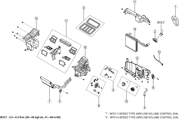
Manual Air Conditioner (L.H.D. (With 23 Screws))
1. Disassemble in the order indicated in the table.
am3zzw00019907
|
|
Step |
Part name |
Disassembly/assembly of main parts |
||
|---|---|---|---|---|
|
Heater core |
Evaporator temperature sensor |
Evaporator |
||
|
1
|
Polyurethane foam
|
X
|
X
|
X
|
|
2
|
Expansion valve
|
-
|
-
|
X
|
|
3
|
Adhesive polyurethane
|
-
|
-
|
-
|
|
4
|
Drain hose
|
-
|
-
|
-
|
|
5
|
Plate A
|
X
|
X
|
X
|
|
6
|
Plate B
|
X
|
X
|
X
|
|
7
|
Heater core
|
X
|
X
|
X
|
|
8
|
Airflow mode link set
|
X (wire clamp)
|
-
|
-
|
|
9
|
Air mix link
|
-
|
-
|
-
|
|
10
|
Blower fan controller (with 7-speed type airflow volume control dial)
|
-
|
-
|
-
|
|
Resistor (with 4-speed type airflow volume control dial)
|
-
|
-
|
-
|
|
|
11
|
A/C case A
|
-
|
X
|
X
|
|
12
|
A/C case B
|
-
|
X
|
X
|
|
13
|
Evaporator temperature sensor (See Evaporator temperature sensor assembly note.)
|
-
|
X
|
X
|
|
14
|
Evaporator
|
-
|
-
|
X
|
|
15
|
A/C case C
|
-
|
-
|
-
|
|
16
|
A/C case D
|
-
|
-
|
-
|
|
17
|
Door damper
|
-
|
-
|
-
|
2. Assemble in the reverse order of disassembly.
Evaporator temperature sensor assembly note
1. Assemble the evaporator temperature sensor as shown in the figure.
am3zzw00019905
|
Full-auto Air Conditioner (R.H.D.)
1. Disassemble in the order indicated in the table.
am3zzw00019908
|
|
Step |
Part name |
Disassembly/assembly of main parts |
||
|---|---|---|---|---|
|
Heater core |
Evaporator temperature sensor |
Evaporator |
||
|
1
|
Polyurethane foam
|
X
|
X
|
X
|
|
2
|
Expansion valve
|
-
|
-
|
X
|
|
3
|
Adhesive polyurethane
|
-
|
-
|
-
|
|
4
|
Drain hose
|
-
|
-
|
-
|
|
5
|
Plate A
|
X
|
X
|
X
|
|
6
|
Plate B
|
X
|
X
|
X
|
|
7
|
Heater core
|
X
|
X
|
X
|
|
8
|
Driver-side air mix actuator (with dual type climate control unit)
|
-
|
-
|
-
|
|
9
|
Driver-side air mix link (with dual type climate control unit)
|
-
|
-
|
-
|
|
10
|
Passenger-side air mix actuator (with dual type climate control unit)
|
-
|
-
|
-
|
|
Air mix actuator (with single type climate control unit)
|
||||
|
11
|
Passenger-side air mix link (with dual type climate control unit)
|
-
|
-
|
-
|
|
Air mix link (with single type climate control unit)
|
||||
|
12
|
Airflow mode actuator
|
-
|
-
|
-
|
|
13
|
Airflow mode link set
|
-
|
-
|
-
|
|
14
|
Blower fan controller
|
-
|
-
|
-
|
|
15
|
A/C case A
|
-
|
X
|
X
|
|
16
|
A/C case B
|
-
|
X
|
X
|
|
17
|
Evaporator temperature sensor (See Evaporator temperature sensor assembly note.)
|
-
|
X
|
X
|
|
18
|
Evaporator
|
-
|
-
|
X
|
|
19
|
A/C case C
|
-
|
-
|
-
|
|
20
|
A/C case D
|
-
|
-
|
-
|
|
21
|
Door damper
|
-
|
-
|
-
|
2. Assemble in the reverse order of disassembly.
Evaporator temperature sensor assembly note
1. Assemble the evaporator temperature sensor as shown in the figure.
am3zzw00019909
|
Manual Air Conditioner (R.H.D.)
1. Disassemble in the order indicated in the table.
am3zzw00019910
|
|
Step |
Part name |
Disassembly/assembly of main parts |
||
|---|---|---|---|---|
|
Heater core |
Evaporator temperature sensor |
Evaporator |
||
|
1
|
Polyurethane foam
|
X
|
X
|
X
|
|
2
|
Expansion valve
|
-
|
-
|
X
|
|
3
|
Adhesive polyurethane
|
-
|
-
|
-
|
|
4
|
Drain hose
|
-
|
-
|
-
|
|
5
|
Plate A
|
X
|
X
|
X
|
|
6
|
Plate B
|
X
|
X
|
X
|
|
7
|
Heater core
|
X
|
X
|
X
|
|
8
|
Airflow mode link set
|
X (wire clamp)
|
-
|
-
|
|
9
|
Air mix link
|
-
|
-
|
-
|
|
10
|
Blower fan controller
|
-
|
-
|
-
|
|
11
|
A/C case A
|
-
|
X
|
X
|
|
12
|
A/C case B
|
-
|
X
|
X
|
|
13
|
Evaporator temperature sensor (See Evaporator temperature sensor assembly note.)
|
-
|
X
|
X
|
|
14
|
Evaporator
|
-
|
-
|
X
|
|
15
|
A/C case C
|
-
|
-
|
-
|
|
16
|
A/C case D
|
-
|
-
|
-
|
|
17
|
Door damper
|
-
|
-
|
-
|
2. Assemble in the reverse order of disassembly.
Evaporator temperature sensor assembly note
1. Assemble the evaporator temperature sensor as shown in the figure.
am3zzw00019909
|