 |
am3zzn00006042
SEAT WARMER SYSTEM
id091300101200
Purpose
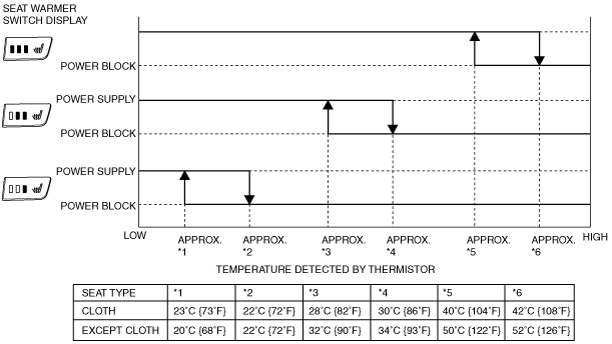
Function
am3zzn00006042
|
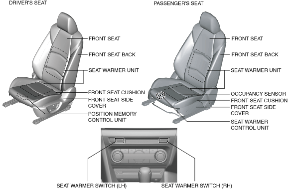
Structural view
am3zzn00006043
|
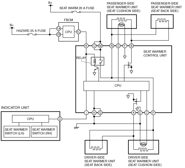
System wiring diagram
am3zzn00004235
|
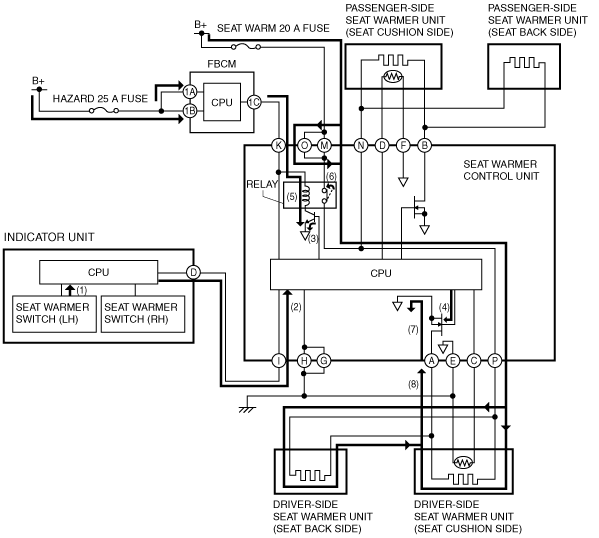
Operation
Ex.) Seat warmer temperature level on cloth-type driver's seat is set at 3
1. The indicator unit determines (1) the average increase temperature of the seat warmer unit by operating the seat warmer switch (driver-side).
2. The indicator unit sends (2) the temperature level "3" signal for the seat warmer unit to the CPU of the seat warmer control unit.
3. When the CPU of the seat warmer control unit receives the operation level "3" signal from the indicator unit, it supplies the base current to the transistor built into the seat warmer control unit (3), and the gate voltage is applied to the FET simultaneously (4).
4. If the base current is supplied, the transistor supplies collector current to the relay coil (5).
5. If collector current is supplied, the relay coil energizes and turns on the relay switch (6).
6. When the gate voltage is applied, the FET completes the circuit between seat warmer control unit terminal A and ground (7).
7. When the relay switch built into the seat warmer control unit turns on and the FET circuit is completed, the driver-side seat warmer unit circuit is completed (8) and the driver-side front seat cushion and seat back warm up.
am3zzn00004236
|
Fail-safe