 |
am3uuw00009998
FRONT OUTER HANDLE REMOVAL/INSTALLATION
id091400510100
Driver's Side
1. Perform the front door glass preparation. (See FRONT DOOR GLASS REMOVAL/INSTALLATION.)
2. Disconnect the negative battery cable. (See NEGATIVE BATTERY CABLE DISCONNECTION/CONNECTION [MZR 1.6].) (See NEGATIVE BATTERY CABLE DISCONNECTION/CONNECTION [SKYACTIV-G 1.5, SKYACTIV-G 2.0, SKYACTIV-G 2.5].) (See NEGATIVE BATTERY CABLE DISCONNECTION/CONNECTION [SKYACTIV-D 2.2].)(See NEGATIVE BATTERY CABLE DISCONNECTION/CONNECTION [SKYACTIV-D 1.5].)
3. Remove the following parts:
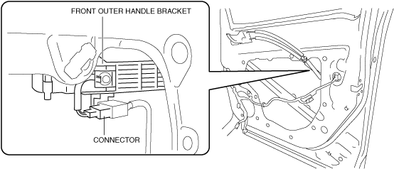
4. Disconnect the keyless antenna connector (with advanced keyless entry system).
am3uuw00009998
|
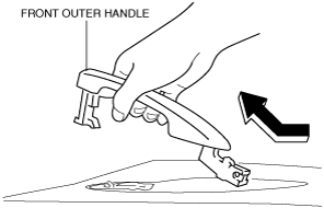
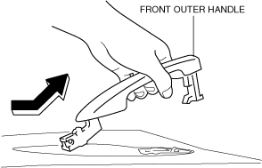
5. While pulling the front outer handle bracket pin in the direction of arrow (1) shown in the figure, pull the front outer handle in the direction of arrow (2) to detach the front outer handle bracket pin and the front outer handle.
am3zzw00014344
|
6. Remove the front outer handle in the direction of the arrow shown in the figure.
am3uuw00010000
|
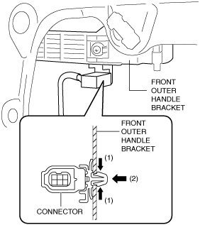
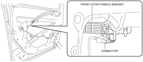
7. While pressing the tabs of the clip in the direction of arrow (1) shown in the figure, press it in the direction of arrow (2) to detach the connector tabs from the front outer handle bracket (with advanced keyless entry system).
am3uuw00010001
|
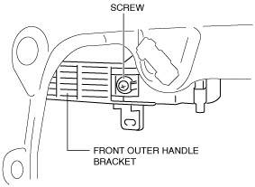
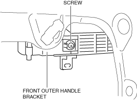
8. Loosen the screw securing the front outer handle bracket.
am3uuw00010002
|
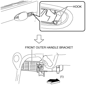
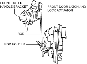
9. Pull the front outer handle bracket in the direction of arrow (1) shown in the figure and detach the front outer handle bracket hooks from the body.
am3uuw00010003
|
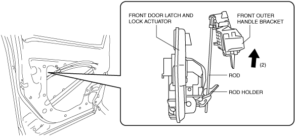
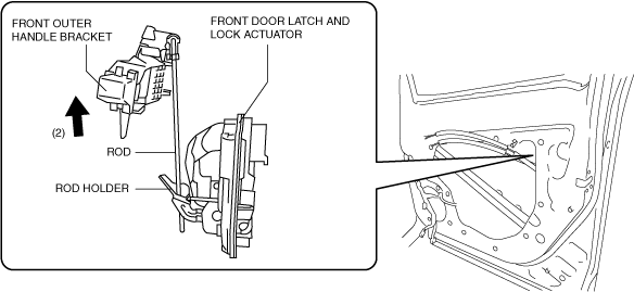
10. Lift the front outer handle bracket in the direction of arrow (2) shown in the figure to pull the rod out of the rod holder. (See Front Outer Handle Bracket Installation Note.)
am3uuw00010004
|
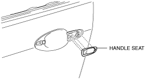
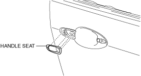
11. Remove the front outer handle bracket.
12. Remove the handle seat from the body.
am3uuw00010005
|
13. Install in the reverse order of removal.
Front Outer Handle Bracket Installation Note
am3uuw00010006
|
Passenger's Side
1. Perform the front door glass preparation. (See FRONT DOOR GLASS REMOVAL/INSTALLATION.)
2. Disconnect the negative battery cable. (See NEGATIVE BATTERY CABLE DISCONNECTION/CONNECTION [MZR 1.6].) (See NEGATIVE BATTERY CABLE DISCONNECTION/CONNECTION [SKYACTIV-G 1.5, SKYACTIV-G 2.0, SKYACTIV-G 2.5].) (See NEGATIVE BATTERY CABLE DISCONNECTION/CONNECTION [SKYACTIV-D 2.2].)(See NEGATIVE BATTERY CABLE DISCONNECTION/CONNECTION [SKYACTIV-D 1.5].)
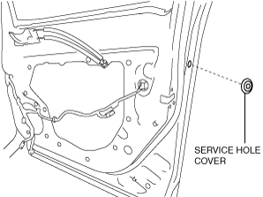
3. Remove the following parts:
4. Remove the service hole cover.
am3zzw00020187
|
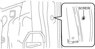
5. Loosen the screw from the front outer handle bracket.
am3zzw00020188
|
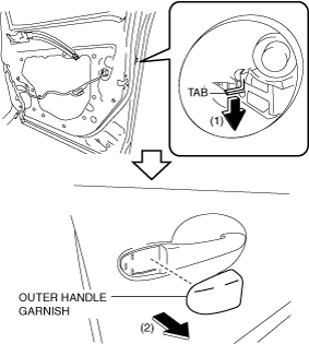
6. While pressing the front outer handle bracket tab in the direction of arrow (1) shown in the figure, pull the outer handle garnish in the direction of arrow (2) to detach the front outer handle bracket from the outer handle garnish.
am3zzw00020189
|
7. Disconnect the keyless antenna connector (with advanced keyless entry system).
am3zzw00020190
|
8. While pulling the front outer handle bracket pin in the direction of arrow (1) shown in the figure, pull the front outer handle in the direction of arrow (2) to detach the front outer handle bracket pin and the front outer handle.
am3zzw00020191
|
9. Remove the front outer handle in the direction of the arrow shown in the figure.
am3zzw00020192
|
10. While pressing the tabs of the clip in the direction of arrow (1) shown in the figure, press it in the direction of arrow (2) to detach the connector tabs from the front outer handle bracket (with advanced keyless entry system).
am3zzw00020193
|
11. Loosen the screw securing the front outer handle bracket.
am3zzw00020194
|
12. Pull the front outer handle bracket in the direction of arrow (1) shown in the figure and detach the front outer handle bracket hooks from the body.
am3zzw00020195
|
13. Lift the front outer handle bracket in the direction of arrow (2) shown in the figure to pull the rod out of the rod holder. (See Front Outer Handle Bracket Installation Note.)
am3zzw00020196
|
14. Remove the front outer handle bracket.
15. Remove the handle seat from the body.
am3zzw00020197
|
16. Install in the reverse order of removal.
Front Outer Handle Bracket Installation Note
am3zzw00020198
|