REAR COMBINATION LIGHT
id091800011800
Purpose
• The rear combination lights are used to signal the following conditions to vehicles/people at the rear.
-
― Rear turn lights: Signals a left or right turn of the vehicle.
― Brake lights: Signals a vehicle stop.
― Taillights: Signals the presence of the vehicle to vehicles/people at the rear during nighttime.
― Rear side marker lights (with rear side marker light): Signals the presence of the vehicle to vehicles/people at the adjacent rear during nighttime.
Function
• The related light turns on or flashes according to the operation of each switch.
|
Operation switch
|
Related light
|
Operation condition
|
|
Light switch (TNS (parking lights))
|
Taillight
|
Turns on
|
|
Rear side marker light (with rear side marker light)
|
|
Brake switch
|
Brake light
|
Turns on
|
|
Turn switch
|
Rear turn light
|
Flashes
|
|
Hazard warning switch
|
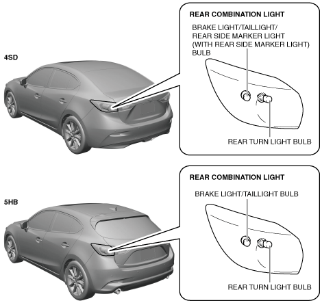
Construction
Bulb type
-
• The rear combination light groups the following parts:
-
― Rear turn light bulb
― Brake light/Taillight bulb (without rear side marker light)
― Brake light/Taillight/Rear side marker light bulb (with rear side marker light)
-
Note
-
• Fogging or condensation on the inside of the rear combination lights may occur, however, it is a natural phenomenon occurring as a result of a temperature difference between the interior and exterior of the combination lights and has no effect on the light performance. Fogging or condensation will dissipate when the temperature inside the rear combination lights rises after the rear turn lights are illuminated and a period of time has elapsed.
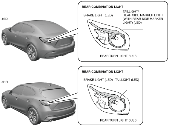
LED type
-
• The rear combination light groups the rear turn light bulb.
• The rear combination light is integrated with the following parts:
-
― Brake light/Taillight (LED) (without rear side marker light)
― Brake light/Taillight/Rear side marker light (LED) (with rear side marker light)
-
Note
-
• Fogging or condensation on the inside of the rear combination lights may occur, however, it is a natural phenomenon occurring as a result of a temperature difference between the interior and exterior of the combination lights and has no effect on the light performance. Fogging or condensation will dissipate when the temperature inside the rear combination lights rises after the rear turn lights are illuminated and a period of time has elapsed.
Operation
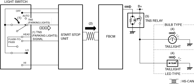
Taillights (without rear side marker light)
1. When the light switch is operated to the TNS (parking lights) position, the start stop unit detects a TNS (parking lights) signal.
2. The start stop unit sends the TNS (parking lights) signal to the front body control module (FBCM) as a CAN signal.
3. When the front body control module (FBCM) receives the TNS (parking lights) signal, it turns the TNS relay on.
4. When the TNS relay turns on, the taillights are illuminated.
Taillights/Rear side marker lights (with rear side marker light)
1. When the light switch is operated to the TNS (parking lights) position, the start stop unit detects a TNS (parking lights) signal.
2. The start stop unit sends the TNS (parking lights) signal to the front body control module (FBCM) as a CAN signal.
3. When the front body control module (FBCM) receives the TNS (parking lights) signal, it turns the TNS relay on.
4. When the TNS relay turns on, the taillights/rear side marker lights are illuminated.
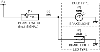
Brake lights
-
Operation due to brake pedal operation
Without smart city brake support (SCBS) and smart brake support (SBS)
-
1. When the brake pedal is depressed, the brake switch (No.1 signal) turns on.
2. When the brake switch (No.1 signal) turns on, current flows from the battery to the brake lights.
3. The brake lights turn on.
With smart city brake support (SCBS) and without smart brake support (SBS)
-
1. When the brake pedal is depressed, the brake switch (No.1 signal) turns on.
2. When the brake switch (No.1 signal) turns on, current flows from the battery to the brake lights.
3. The brake lights turn on.
With smart brake support (SBS)
-
1. When the brake pedal is depressed, the brake switch (No.1 signal) turns on.
2. When the brake switch (No.1 signal) turns on, a brake switch (No.1 signal) on signal is input to the brake light unit.
3. When the brake light unit receives a brake switch (No.1 signal) on signal, it supplies current to the brake lights.
4. The brake lights turn on.
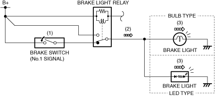
Operation due to operation request signal from rear body control module (RBCM)
-
Note
-
With smart city brake support (SCBS) and without smart brake support (SBS)
-
1. When the operation conditions are met, the rear body control module (RBCM) turns on the transistor inside the rear body control module (RBCM).
2. When the transistor inside the rear body control module (RBCM) turns on, the brake light relay turns on.
3. When the brake light relay turns on, current flows from the battery to the brake lights.
4. The brake lights turn on.
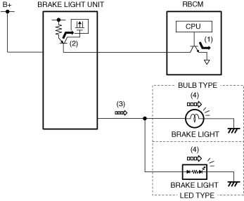
With smart brake support (SBS)
-
1. When the operation conditions are met, the rear body control module (RBCM) turns on the transistor inside the rear body control module (RBCM).
2. When the transistor inside the rear body control module (RBCM) turns on, the transistor inside the brake light unit turns on.
3. When the transistor inside the brake light unit turns on, current flows to the brake lights.
4. The brake lights turn on.
Rear turn lights
-
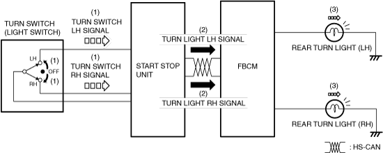
Turn light system
-
1. When the turn switch is operated to the LH or RH position, the start stop unit detects a turn switch LH or RH signal.
2. The start stop unit sends the turn switch LH or RH signal to the front body control module (FBCM) via CAN communication as a turn light LH or RH signal.
3. When the front body control module (FBCM) receives the turn light LH or RH signal, the rear turn light (LH) or (RH) flashes.
-
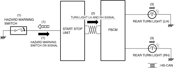
Hazard warning system
-
1. When the hazard warning switch is turned on, the start stop unit detects a hazard warning switch on signal.
2. The start stop unit sends the hazard warning switch on signal to the front body control module (FBCM) via CAN communication as a turn light LH and RH signals.
3. When the front body control module (FBCM) receives the turn light LH and RH signals, it flashes the rear turn lights (LH) and (RH).
Fail-safe
• Not applicable