 |
am3zzn00005961
WINDSHIELD WIPER/WASHER SYSTEM
id091900001900
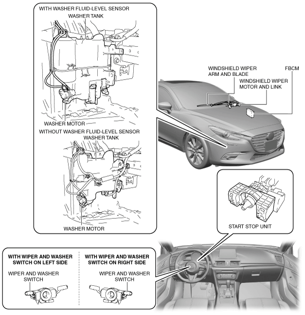
Outline
Structural View
am3zzn00005961
|
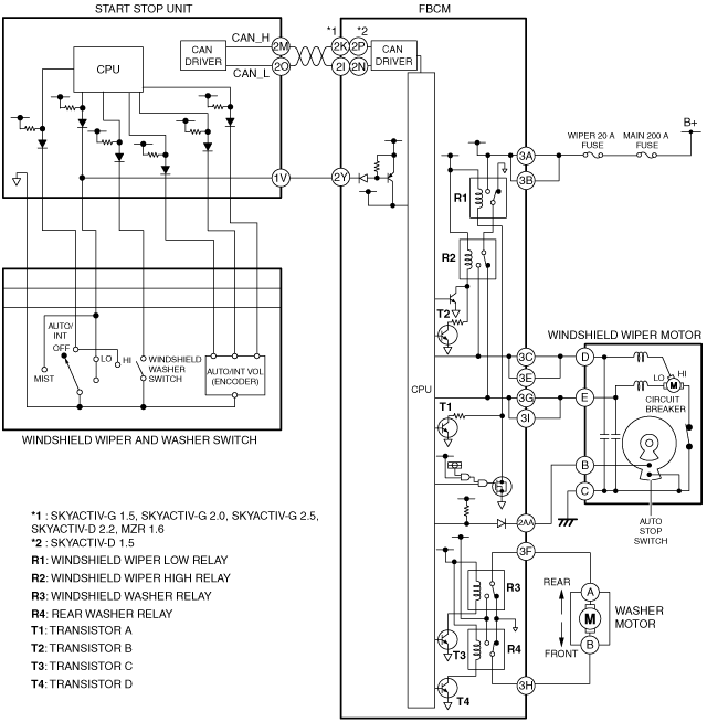
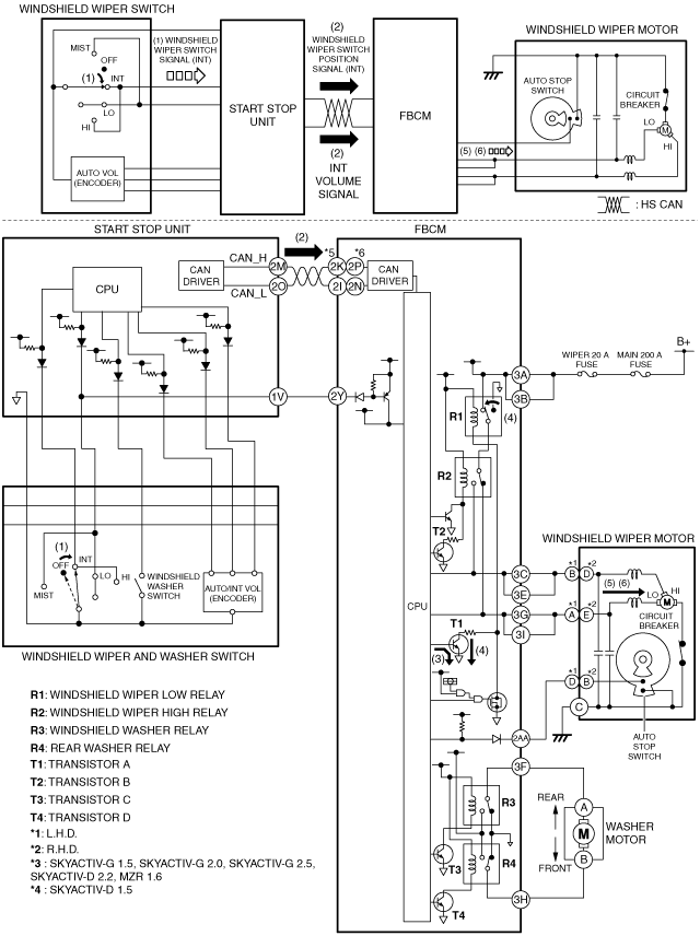
System Wiring Diagram
With wiper and washer switch on left side
am3zzn00005962
|
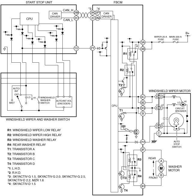
With wiper and washer switch on right side
am3zzn00006393
|
Operation
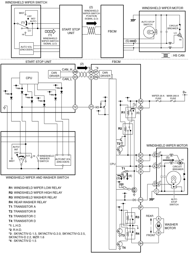
Continuous low operation
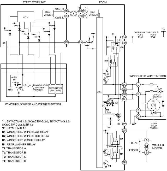
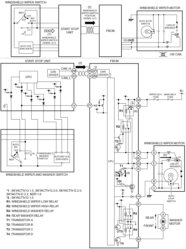
1. When the windshield wiper switch is moved to the LO position with the ignition switched ON (engine off or on), the start stop unit detects a windshield wiper switch signal (LO).
2. When the start stop unit detects the windshield wiper switch signal (LO), it send a windshield wiper switch position signal (LO) to the front body control module (FBCM) as a CAN signal.
3. When the front body control module (FBCM) receives the windshield wiper switch position signal (LO), it supplies the base current from the internal CPU to transistor A, and turns transistor A on.
4. When the transistor A is turned on, collector current flows from the internal power supply, turning the windshield wiper low relay on.
5. When the windshield wiper low relay is turned on, current flows from the battery to the windshield wiper motor and the windshield wipers operate continuously at low speed.
With wiper and washer switch on left side
am3zzn00006394
|
With wiper and washer switch on right side
am3zzn00006395
|
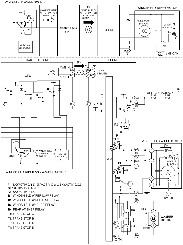
Continuous high operation
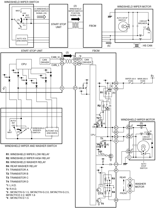
1. When the windshield wiper switch is moved to the HI position with the ignition switched ON (engine off or on), the start stop unit detects a windshield wiper switch signal (HI).
2. When the start stop unit detects the windshield wiper switch signal (HI), it send a windshield wiper switch position signal (HI) to the front body control module (FBCM) as a CAN signal.
3. When the front body control module (FBCM) receives the windshield wiper switch position signal (HI), it supplies the base current from the internal CPU to transistors A and B, and turns transistors A and B on.
4. When the transistors A and B are turned on, collector current flows from the internal power supply, turning the windshield wiper low relay and windshield wiper high relay on.
5. When the windshield wiper low relay and windshield wiper high relay are turned on, current flows from the battery to the windshield wiper motor and the windshield wipers operate continuously at high speed.
With wiper and washer switch on left side
am3zzn00006396
|
With wiper and washer switch on right side
am3zzn00006397
|
Auto-stop operation
1. The auto-stop switch inside the windshield wiper motor operates as follows according to the operation position of the windshield wipers.
2. When the windshield wiper switch is in the OFF position during windshield wiper operation, the windshield wipers operate continuously because the auto-stop switch is off.
3. The auto-stop switch turns on when the windshield wipers move to the park position.
4. When the front body control module (FBCM) detects that the auto-stop switch is on, it stops the base current to transistor A and turns off transistor A.
5. When transistor A is turned off, collector current stops and the windshield wiper low relay turns off.
6. When the windshield wiper low relay is turned off, the windshield wipers stop at the park position.
With wiper and washer switch on left side
am3zzn00005968
|
With wiper and washer switch on right side
am3zzn00006398
|
One-touch wiper operation
1. When the windshield wiper switch is moved up (MIST position) with the ignition switched ON (engine off or on), the start stop unit detects a windshield wiper switch signal (LO).
2. When the start stop unit detects a windshield wiper switch signal (LO), it send a windshield wiper switch position signal (LO) to the front body control module (FBCM) as a CAN signal.
3. When the front body control module (FBCM) receives the windshield wiper switch position signal (LO), it supplies the base current from the internal CPU to transistor A, and turns transistor A on.
4. When the transistor A is turned on, collector current flows from the internal power supply, turning the windshield wiper low relay on.
5. When the windshield wiper low relay is turned on, current flows from the battery to the windshield wiper motor and the windshield wipers operate continuously at low speed.
With wiper and washer switch on left side
am3zzn00006399
|
With wiper and washer switch on right side
am3zzn00006400
|
Intermittent wiper operation (without auto wiper system)
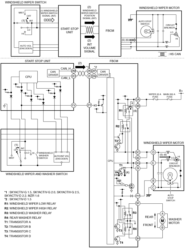
1. When the windshield wiper switch is moved to the INT position with the ignition switched ON (engine off or on), the start stop unit detects a windshield wiper switch signal (INT).
2. When the start stop unit detects a windshield wiper switch signal (INT), it send a windshield wiper switch position signal (INT) and an INT volume signal to the front body control module (FBCM) as CAN signals.
3. When the front body control module (FBCM) receives the windshield wiper switch position signal (INT), it supplies the base current from the internal CPU to transistor A, and collector current flows from the internal power supply, and turns transistor A on.
4. When the transistor A is turned on, collector current flows from the internal power supply, turning the windshield wiper low relay on.
5. When the windshield wiper low relay is turned on, current flows from the battery to the windshield wiper motor and the windshield wipers operate continuously at low speed.
6. The windshield wipers stop at the park position due to the auto-stop operation, and after a certain period of time has elapsed, which was calculated based on the INT volume signal, the front body control module (FBCM) operates the windshield wipers at a low speed. By repeating this, the windshield wipers operate intermittently.
With wiper and washer switch on left side
am3zzn00006401
|
With wiper and washer switch on right side
am3zzn00006402
|
Auto wiper operation (with auto wiper system)
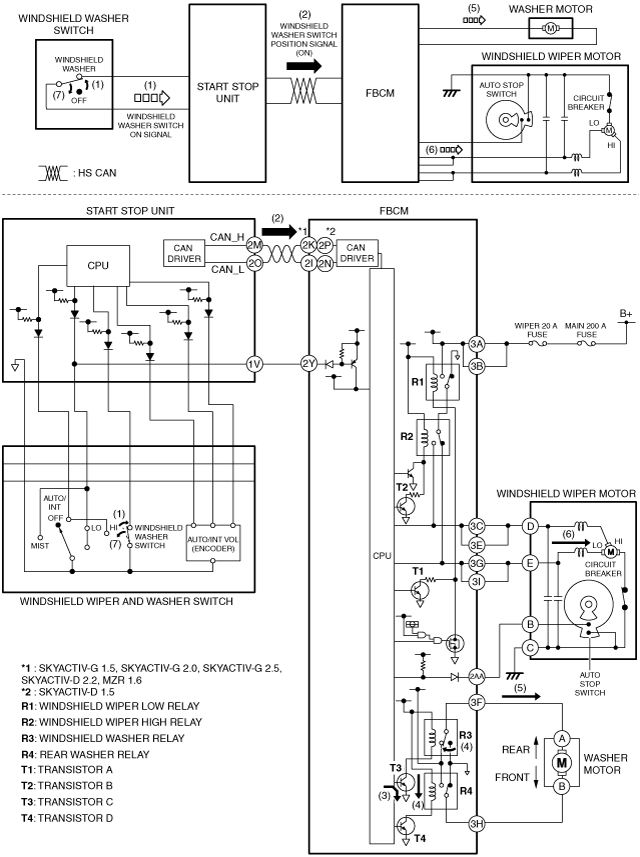
Synchronized washer and wiper operation
1. When the windshield washer switch is turned on with the ignition switched ON (engine off or on) and the windshield wipers not operated, the start stop unit detects a windshield washer switch ON signal.
2. When the start stop unit detects a windshield washer switch ON signal, it send a windshield washer switch position signal (ON) to the front body control module (FBCM) as a CAN signal.
3. When the front body control module (FBCM) receives the windshield washer switch position signal (ON), it supplies the base current from the internal CPU to transistor C, and collector current flows from the internal power supply, and turns transistor C on.
4. When the transistor C is turned on, collector current flows from the internal power supply, turning the windshield washer relay on.
5. When the windshield washer relay is turned on, current flows from the power supply inside the front body control module (FBCM) to the washer motor and the washer motor operates, and washer fluid is sprayed from the windshield washer nozzles.
6. When the front body control module (FBCM) receives the windshield washer switch position signal (ON) for a certain period of time, it operates the windshield wipers at low speed.
7. When the windshield washer switch is turned off, the operation stops after the windshield wipers operate two times.
With wiper and washer switch on left side
am3zzn00005974
|
With wiper and washer switch on right side
am3zzn00006403
|
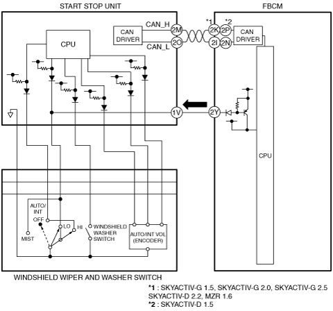
LO/HI Detection Function
With wiper and washer switch on left side
am3zzn00005976
|
With wiper and washer switch on right side
am3zzn00005977
|