 |
am3zzn00005978
REAR WIPER/WASHER SYSTEM
id091900002000
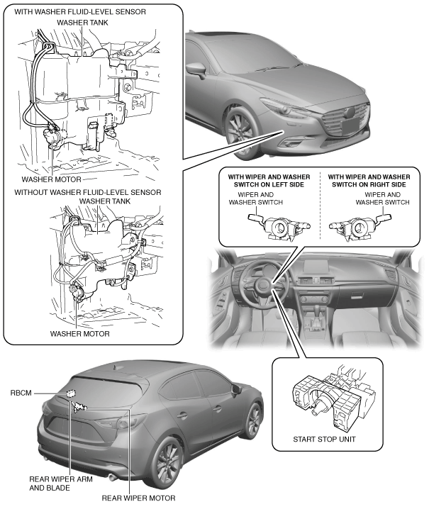
Outline
Structural View
am3zzn00005978
|
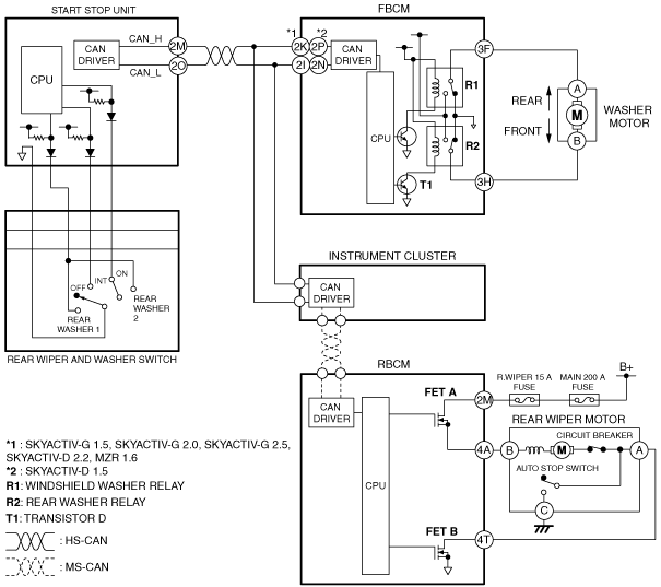
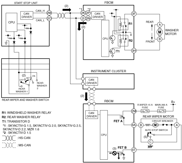
System Wiring Diagram
With wiper and washer switch on left side
am3zzn00005979
|
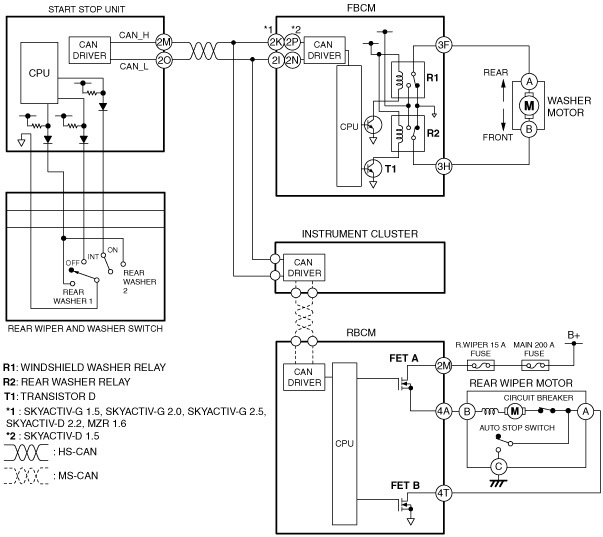
With wiper and washer switch on right side
am3zzn00006404
|
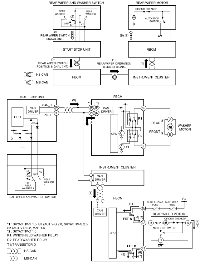
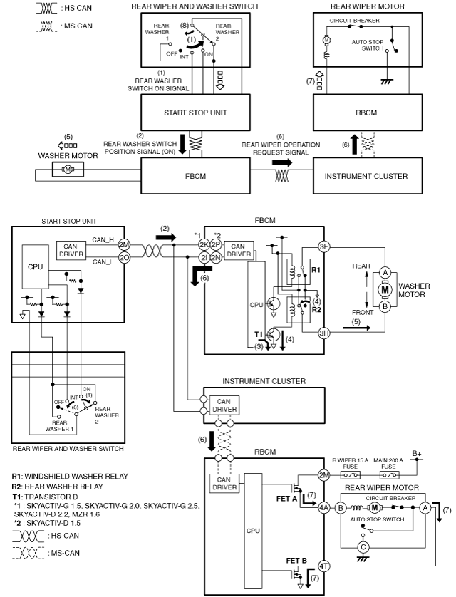
Operation
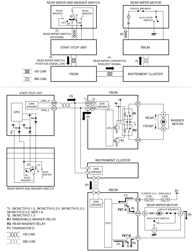
Continuous operation
1. When with the ignition switched ON (engine off or on), the rear body control module (RBCM) turns FET A on.
2. When the rear wiper and washer switch is turned to the ON position, the start stop unit detects a rear wiper switch ON signal.
3. When the start stop unit detects a rear wiper switch ON signal, it send a rear wiper switch position signal (ON) to the front body control module (FBCM) as a CAN signal.
4. When the front body control module (FBCM) receives the rear wiper switch position signal (ON), it sends a rear wiper operation request signal to the rear body control module (RBCM) via the instrument cluster as a CAN signal.
5. When the rear body control module (RBCM) receives the rear wiper operation request signal, it supplies the gate current from the internal CPU to FET B, and turns FET B on.
6. When FET B is turned on, and current flows from the battery to the rear wiper motor and the rear wiper operates continuously.
With wiper and washer switch on left side
am3zzn00005981
|
With wiper and washer switch on right side
am3zzn00006405
|
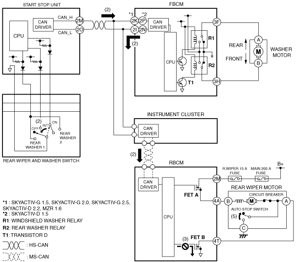
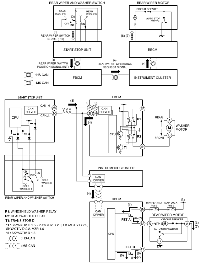
Auto-stop operation
1. The auto-stop switch inside the rear wiper motor operates as follows according to the operation position of the rear wipers.
2. When the rear wiper and washer switch is in the OFF position during rear wiper operation, the rear wiper operation request signal sent to the rear body control module (RBCM) via the instrument cluster from the front body control module (FBCM) turns off.
3. When the rear wiper operation request signal turns off, the rear body control module (RBCM) turns the FET B off.
4. The rear wiper operates continuously because the auto-stop switch is on.
5. The auto-stop switch in the rear wiper motor turns off if the rear wiper stops at the correct position, and the rear wiper stops based on this.
With wiper and washer switch on left side
am3zzn00005983
|
With wiper and washer switch on right side
am3zzn00006406
|
Intermittent wiper operation
1. When the ignition is switched ON (engine on or off), the rear body control module (RBCM) turns FET A on.
2. When the rear wiper and washer switch is moved to the INT position, the start stop unit detects a rear wiper switch signal (INT).
3. When the start stop unit detects a rear wiper switch signal (INT), it send a rear wiper switch position signal (INT) to the front body control module (FBCM) as a CAN signal.
4. When the front body control module (FBCM) receives the rear wiper switch position signal (INT), it sends a rear wiper operation request signal to the rear body control module (RBCM) via the instrument cluster as a CAN signal.
5. When the rear body control module (RBCM) receives the rear wiper operation request signal, it supplies the gate current from the internal CPU to FET B, and turns FET B on.
6. When FET B is turned on, and current flows from the battery to the rear wiper motor and the rear wiper operates continuously.
7. The front body control module (FBCM) sends a rear wiper operation request signal to the rear body control module (RBCM) via the instrument cluster at regular intervals. Due to this, the rear wiper operates intermittently.
With wiper and washer switch on left side
am3zzn00005985
|
With wiper and washer switch on right side
am3zzn00006407
|
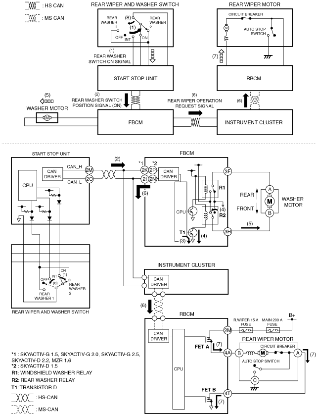
Synchronized washer and wiper operation
1. When the rear wiper and washer switch is turned to the rear washer 2 position with the ignition switched ON (engine off or on), the start stop unit detects a rear washer switch ON signal.
2. When the start stop unit detects a rear washer switch ON signal, it send a rear washer switch position signal (ON) to the front body control module (FBCM) as a CAN signal.
3. When the front body control module (FBCM) receives the rear washer switch position signal (ON), it supplies the base current from the internal CPU to transistor D, and collector current flows from the internal power supply, and turns transistor D on.
4. When the transistor D is turned on, collector current flows from the internal power supply, turning the rear washer relay on.
5. When the rear washer relay is turned on, current flows to the washer motor and the washer motor operates, and washer fluid is sprayed from the rear washer nozzle.
6. When the front body control module (FBCM) receives the rear washer switch position signal (ON) for a certain period of time, it sends a rear wiper operation request signal to the rear body control module (RBCM) via the instrument cluster as a CAN signal.
7. When the rear body control module (RBCM) receives the rear wiper operation request signal, it operates the rear wiper.
8. When the rear washer switch is turned off, the rear wiper stops after it operates for approx. 2.6 s.
With wiper and washer switch on left side
am3zzn00005987
|
With wiper and washer switch on right side
am3zzn00006408
|