FUEL GAUGE SENDER UNIT INSPECTION
id092200012100
-
Warning
-
• Always keep sparks and flames away from fuel when servicing the fuel system. Fuel can be easily ignited which could cause serious injury or death, and damage to equipment.
• Fuel line spills and leakage from the pressurized fuel system are dangerous. Fuel can ignite and cause serious injury or death and damage. Fuel can also irritate skin and eyes. To prevent this, always complete the Fuel Line Safety Procedure, while referring to the BEFORE SERVICE PRECAUTION.
• A person charged with static electricity could cause a fire or explosion, resulting in death or serious injury. Before draining fuel, make sure to discharge static electricity by touching a vehicle.
-
Caution
-
• If the fuel gauge level indicates 3/4 or more, the fuel surface is higher than the fuel pump unit and fuel gauge sender unit installation surface. If servicing is performed under this condition, fuel leakage could result. Always drain the fuel before performing the operation and keep the fuel in the fuel tank at less than half.
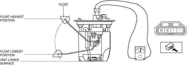
Fuel gauge sender unit connector 4-pin type
SKYACTIV-G 1.5, SKYACTIV-G 2.0, SKYACTIV-G 2.5, MZR 1.6, SKYACTIV-D 1.5 (LHD)
-
Note
-
1. Verify that the resistance at fuel gauge sender unit terminals D and C is as follows according to the height of the float.
-
Resistance when float is in the highest position
-
• 18.5—21.5 ohms
-
Resistance when float is in the lowest position
-
• 197—203 ohms
-
• If the resistance is not within the specification, replace the fuel gauge sender unit.
SKYACTIV-D 1.5(RHD), SKYACTIV-D 2.2
1. Complete the “BEFORE SERVICE PRECAUTION”. (See BEFORE SERVICE PRECAUTION [SKYACTIV-D 1.5].) (See BEFORE SERVICE PRECAUTION [SKYACTIV-D 2.2].)
2. If the fuel gauge level indicates 3/4 or more, refer to the “FUEL DRAINING PROCEDURE” and drain the fuel. (See FUEL DRAINING PROCEDURE [SKYACTIV-D 1.5].) (See FUEL DRAINING PROCEDURE [SKYACTIV-D 2.2].)
3. Disconnect the negative battery cable. (See NEGATIVE BATTERY CABLE DISCONNECTION/CONNECTION [SKYACTIV-D 1.5].) (See NEGATIVE BATTERY CABLE DISCONNECTION/CONNECTION [SKYACTIV-D 2.2].)
4. Remove the rear seat cushion. (See REAR SEAT CUSHION REMOVAL/INSTALLATION.)
5. Remove the fuel gauge sender unit. (See FUEL GAUGE SENDER UNIT REMOVAL/INSTALLATION.)
6. Verify that the resistance at fuel gauge sender unit terminals A and C is as follows according to the height of the float.
-
Resistance when float is in the highest position
-
• 18.5—21.5 ohms
-
Resistance when float is in the lowest position
-
• 197—203 ohms
-
• If the resistance is not within the specification, replace the fuel gauge sender unit.
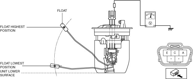
Fuel gauge sender unit connector 5-pin type
-
Note
-
1. Apply 5 V to fuel gauge sender unit terminals A.
2. Verify the voltage of fuel gauge sender unit terminal E.
-
Voltage when float is in the highest position
-
• 4.4—4.6 V
-
Voltage when float is in the lowest position
-
• 0.4—0.6 V
• If the voltage is not within the specification, replace the fuel gauge sender unit.