FUEL GAUGE
id092200032700
Purpose
• The fuel gauge notifies the user of the amount of remaining fuel.
Function
• The instrument cluster calculates the amount of fuel in the fuel tank based on the following CAN signals and displays the fuel gauge segments.
-
― Fuel gauge sender unit voltage signal sent from rear body control module (RBCM)
― Fuel injection amount signal, vehicle speed signal sent from PCM
Fuel gauge flicker prevention function
-
• When the instrument cluster determines that the vehicle is being driven, it retards the response with which the calculated amount of fuel is reflected to the fuel gauge. As a result, fuel gauge flicker caused by the variation of fuel surface during driving is prevented.
Refuel determination function
-
• If the amount of fuel is changed by 5 L {1 US gal, 1 Imp gal}/2 L {0.5 US gal, 0.4 Imp gal}*1 or more while the vehicle is stopped, the instrument cluster determines that the vehicle is refueled and displays the fuel gauge segments based on the fuel gauge sender unit voltage signal from the rear body control module (RBCM).
*1 :5 L {1 US gal, 1 Imp gal} when the number of fuel gauge segments is 14 or less/2 L {0.5 US gal, 0.4 Imp gal}when the number of fuel gauge segments is 15 or more.
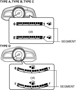
Construction
• The fuel gauge is displayed in the LCD of the instrument cluster.
• The fuel gauge is consists of 15 segments.
Operation
Fuel gauge sender unit connector 4-pin type
-
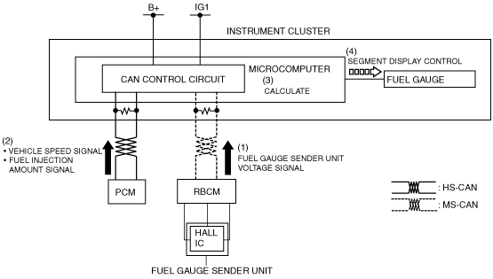
1. The fuel gauge sender unit resistance changes according to the float position on the fuel surface in the fuel tank.
2. When the ignition is switched ON (engine off or on), the rear body control module (RBCM) converts the resistance from the fuel gauge sender unit to voltage and sends it to the instrument cluster as a fuel gauge sender unit voltage signal (1).
3. The instrument cluster receives the fuel gauge sender unit voltage signal from the rear body control module (RBCM), and it also receives the fuel injection amount control signal and vehicle speed signal from the PCM (2).
4. The instrument cluster calculates the amount of fuel in the fuel tank based on the signals (3).
5. The instrument cluster displays/turns off the fuel gauge segments according to the calculation result (4).
Fuel gauge sender unit connector 5-pin type
-
1. The magnetic field applied to the Hall element of the fuel gauge sender unit changes according to the float position on the fuel surface in the fuel tank, and the output voltage changes according to the magnetic field.
2. When the ignition is switched ON (engine off or on), the rear body control module (RBCM) sends the voltage from the fuel gauge sender unit to the instrument cluster as a fuel gauge sender unit voltage signal (1).
3. The instrument cluster receives the fuel gauge sender unit voltage signal from the rear body control module (RBCM), and it also receives the fuel injection amount control signal and vehicle speed signal from the PCM (2).
4. The instrument cluster calculates the amount of fuel in the fuel tank based on the signals (3).
5. The instrument cluster displays/turns off the fuel gauge segments according to the calculation result (4).
Fail-safe
• Function not equipped.