 |
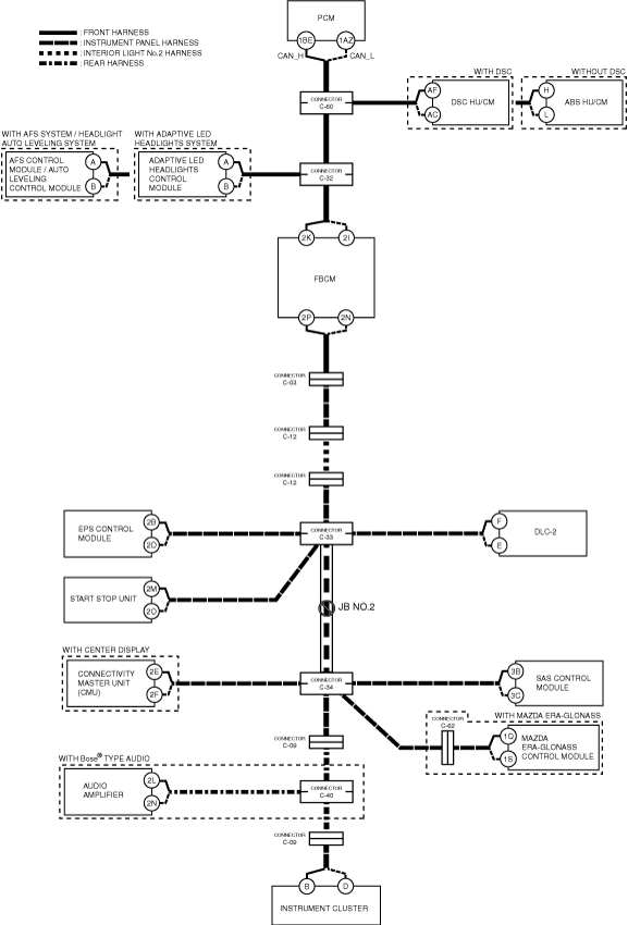
am3zzw00019449
DETERMINING OPEN CIRCUIT LOCATION (HS-CAN) [MZR 1.6 (L.H.D.)]
id100232000400
1. Verify the CAN system-related module DTCs and the failed module on the M-MDS screen.
2. Apply the communication error DTC and the failed module to DTC output pattern and malfunctioning location, and select the possible cause for the diagnostic result and the reference for the inspection item. (See DTC Output Pattern And Malfunctioning Location.)
3. Inspect the possible cause and inspection item of the applicable malfunctioning part.
4. After repairs, return to CONTROLLER AREA NETWORK (CAN) MALFUNCTION DIAGNOSIS FLOW, and verify that the repairs have been completed. (See CONTROLLER AREA NETWORK (CAN) MALFUNCTION DIAGNOSIS FLOW [MZR 1.6 (L.H.D.)].)
DTC Output Pattern And Malfunctioning Location
|
M-MDS display |
DTC |
DTC output pattern and malfunctioning location |
|||||||||||||||
|---|---|---|---|---|---|---|---|---|---|---|---|---|---|---|---|---|---|
|
DTC output module |
|||||||||||||||||
|
PCM
(PCM)
|
U0121:00
|
|
×
|
|
|
|
|
|
|
|
|
|
|
|
|
|
|
|
U0131:00
|
|
|
|
|
|
|
|
×
|
|
|
|
|
|
|
|
||
|
U0140:00
|
|
|
|
|
|
×
|
|
|
|
|
|
|
|
|
|
||
|
U0151:00
|
|
|
|
|
|
|
|
|
|
×
|
|
×
|
|
|
|
||
|
U0155:00
|
|
|
|
|
|
|
|
|
|
×
|
|
|
×
|
|
×
|
||
|
U0214:00
|
|
|
|
|
|
|
|
|
×
|
|
|
|
|
|
|
||
|
ABS*1
(DSC HU/CM)
|
U0100:00
|
×
|
|
|
|
|
|
|
|
|
|
|
|
|
|
|
|
|
U0131:00
|
|
|
|
|
|
|
|
×
|
|
|
|
|
|
|
|
||
|
U0151:00
|
|
|
|
|
|
|
|
|
|
×
|
|
×
|
|
|
|
||
|
U0155:00
|
|
|
|
|
|
|
|
|
|
×
|
|
|
×
|
|
×
|
||
|
ABS*2
(ABS HU/CM)
|
U0100:00
|
×
|
|
|
|
|
|
|
|
|
|
|
|
|
|
|
|
|
U0151:00
|
|
|
|
|
|
|
|
|
|
×
|
|
×
|
|
|
|
||
|
U0155:00
|
|
|
|
|
|
|
|
|
|
×
|
|
|
×
|
|
×
|
||
|
AFS/ALM*3
(Adaptive LED headlights control module)
|
U0100:00
|
×
|
|
×
|
|
|
|
|
|
|
|
|
|
|
|
|
|
|
U0121:00
|
|
×
|
×
|
|
|
|
|
|
|
|
|
|
|
|
|
||
|
U0131:00
|
|
|
|
|
|
|
|
×
|
|
|
|
|
|
|
|
||
|
U0140:00
|
|
|
|
|
|
×
|
|
|
|
|
|
|
|
|
|
||
|
U0155:00
|
|
|
|
|
|
|
|
|
|
×
|
|
|
×
|
|
×
|
||
|
U0214:00
|
|
|
|
|
|
|
|
|
×
|
|
|
|
|
|
|
||
|
AFS/ALM*4
(AFS control module / auto leveling control module)
|
U0100:00
|
×
|
|
×
|
|
|
|
|
|
|
|
|
|
|
|
|
|
|
U0131:00
|
|
|
|
|
|
|
|
×
|
|
|
|
|
|
|
|
||
|
U0140:00
|
|
|
|
|
|
×
|
|
|
|
|
|
|
|
|
|
||
|
U0155:00
|
|
|
|
|
|
|
|
|
|
×
|
|
|
×
|
|
×
|
||
|
F_BCM
(Front body control module (FBCM))
|
U0100:00
|
×
|
|
×
|
|
×
|
|
|
|
|
|
|
|
|
|
|
|
|
U0121:00
|
|
×
|
×
|
|
×
|
|
|
|
|
|
|
|
|
|
|
||
|
U0151:00
|
|
|
|
|
|
|
|
|
|
×
|
|
×
|
|
|
|
||
|
U0155:00
|
|
|
|
|
|
|
|
|
|
×
|
|
|
×
|
|
×
|
||
|
U0182:00
|
|
|
|
×
|
×
|
|
|
|
|
|
|
|
|
|
|
||
|
U0214:00
|
|
|
|
|
|
|
|
|
×
|
|
|
|
|
|
|
||
|
EPS
(EPS control module
|
U0100:00
|
×
|
|
×
|
|
×
|
|
×
|
|
|
|
|
|
|
|
|
|
|
U0121:00
|
|
×
|
×
|
|
×
|
|
×
|
|
|
|
|
|
|
|
|
||
|
U0155:00
|
|
|
|
|
|
|
|
|
|
×
|
|
|
×
|
|
×
|
||
|
U0214:00
|
|
|
|
|
|
|
|
|
×
|
|
|
|
|
|
|
||
|
SSU
(Start stop unit)
|
U0100:00
|
×
|
|
×
|
|
×
|
|
×
|
|
|
|
|
|
|
|
|
|
|
U0121:00
|
|
×
|
×
|
|
×
|
|
×
|
|
|
|
|
|
|
|
|
||
|
U0121:87
|
|
×
|
×
|
|
×
|
|
×
|
|
|
|
|
|
|
|
|
||
|
U0131:00
|
|
|
|
|
|
|
|
×
|
|
|
|
|
|
|
|
||
|
U0140:00
|
|
|
|
|
|
×
|
×
|
|
|
|
|
|
|
|
|
||
|
U0146:00
|
|
|
|
|
|
|
|
|
|
×
|
|
|
×
|
|
×
|
||
|
U0151:00
|
|
|
|
|
|
|
|
|
|
×
|
|
×
|
|
|
|
||
|
U0155:00
|
|
|
|
|
|
|
|
|
|
×
|
|
|
×
|
|
×
|
||
|
CMU*5
(Connectivity master unit (CMU))
|
U0100:00
|
×
|
|
×
|
|
×
|
|
×
|
|
|
|
|
|
|
|
|
|
|
U0121:00
|
|
×
|
×
|
|
×
|
|
×
|
|
|
|
|
|
|
|
|
||
|
U0131:00
|
|
|
|
|
|
|
|
×
|
|
|
|
|
|
|
|
||
|
U0140:00
|
|
|
|
|
|
×
|
×
|
|
|
|
|
|
|
|
|
||
|
U0151:00
|
|
|
|
|
|
|
|
|
|
|
|
×
|
|
|
|
||
|
U0155:00
|
|
|
|
|
|
|
|
|
|
|
|
|
×
|
|
×
|
||
|
U0182:00
|
|
|
|
×
|
×
|
|
×
|
|
|
|
|
|
|
|
|
||
|
U0214:00
|
|
|
|
|
|
|
|
|
×
|
|
|
|
|
|
|
||
|
RCM
(SAS control module)
|
U0155:00
|
|
|
|
|
|
|
|
|
|
|
|
|
×
|
|
×
|
|
|
DCM*6
(MAZDA ERA-GLONASS control module)
|
U0100:00
|
×
|
|
×
|
|
×
|
|
×
|
|
|
|
|
|
|
|
|
|
|
U0121:00
|
|
×
|
×
|
|
×
|
|
×
|
|
|
|
|
|
|
|
|
||
|
U0151:00
|
|
|
|
|
|
|
|
|
|
|
|
×
|
|
|
|
||
|
U0155:00
|
|
|
|
|
|
|
|
|
|
|
|
|
×
|
|
×
|
||
|
IC
(Instrument cluster)
|
U0100:00
|
×
|
|
×
|
|
×
|
|
×
|
|
|
|
|
|
|
|
|
|
|
U0121:00
|
|
×
|
×
|
|
×
|
|
×
|
|
|
|
|
|
|
|
|
||
|
U0131:00
|
|
|
|
|
|
|
|
×
|
|
|
|
|
|
|
|
||
|
U0140:00
|
|
|
|
|
|
×
|
×
|
|
|
|
|
|
|
|
|
||
|
U0151:00
|
|
|
|
|
|
|
|
|
|
|
|
×
|
|
|
|
||
|
U0156:00
|
|
|
|
|
|
|
|
|
|
|
×
|
|
|
|
|
||
|
U0182:00
|
|
|
|
×
|
×
|
|
×
|
|
|
|
|
|
|
|
|
||
|
U0214:00
|
|
|
|
|
|
|
|
|
×
|
|
|
|
|
|
|
||
|
M-MDS display module
|
[Fail] display pattern
|
||||||||||||||||
|
PCM
|
×
|
|
×
|
|
×
|
|
×
|
|
|
|
|
|
|
|
|
||
|
ABS*1, *2
|
|
×
|
×
|
|
×
|
|
×
|
|
|
|
|
|
|
|
|
||
|
AFS/ALM*3, *4
|
|
|
|
×
|
×
|
|
×
|
|
|
|
|
|
|
|
|
||
|
F_BCM
|
|
|
|
|
|
×
|
×
|
|
|
|
|
|
|
|
|
||
|
EPS
|
|
|
|
|
|
|
|
×
|
|
|
|
|
|
|
|
||
|
SSU
|
|
|
|
|
|
|
|
|
×
|
|
|
|
|
|
|
||
|
CMU*5
|
|
|
|
|
|
|
|
|
|
×
|
×
|
|
|
|
|
||
|
RCM
|
|
|
|
|
|
|
|
|
|
×
|
|
×
|
|
|
|
||
|
DCM*6
|
|
|
|
|
|
|
|
|
|
×
|
|
|
×
|
|
|||
|
AM*7
|
|
|
|
|
|
|
|
|
|
×
|
|
|
×
|
×
|
|
||
|
IC
|
|
|
|
|
|
|
|
|
|
×
|
|
|
×
|
|
×
|
||
|
Diagnostic result
|
|||||||||||||||||
|
Possible cause and inspection item
|
|||||||||||||||||
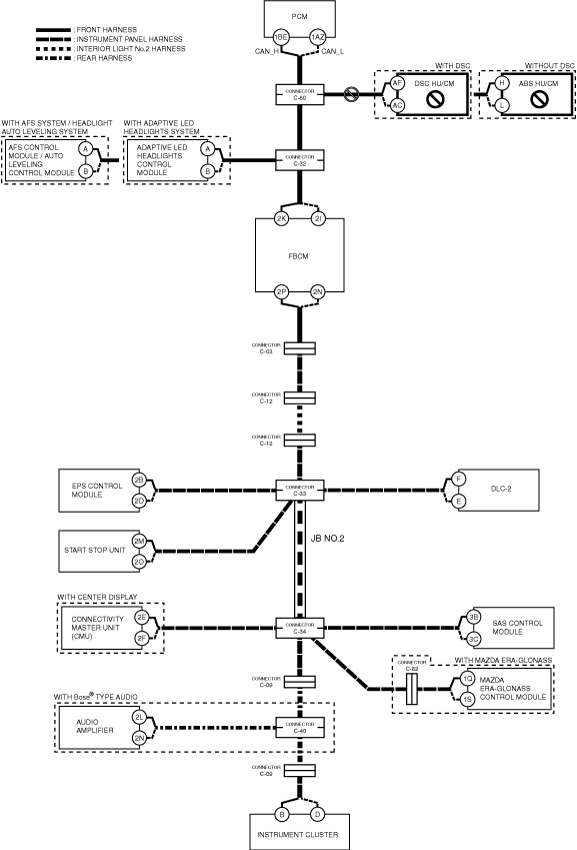
A
Possible cause
System wiring diagram
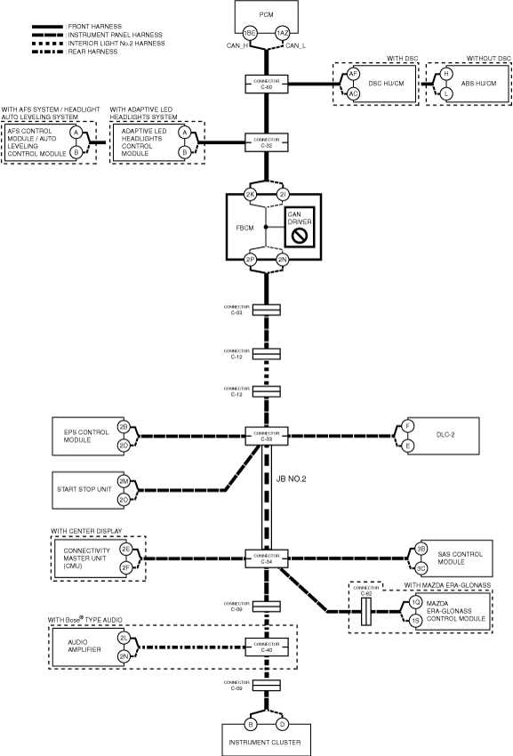
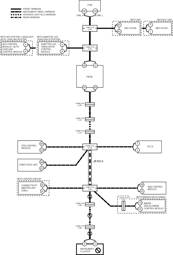
am3zzw00019449
|
Inspection item
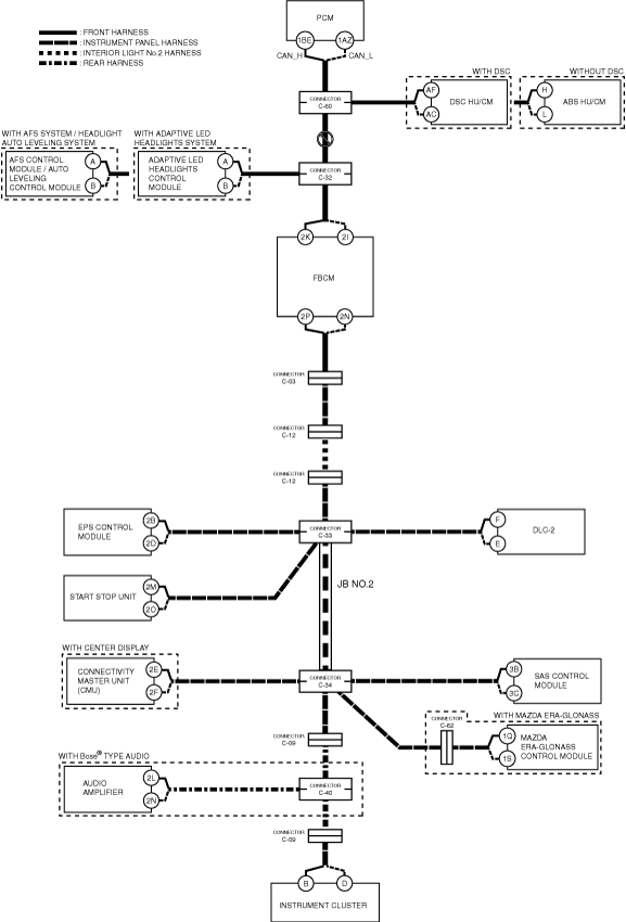
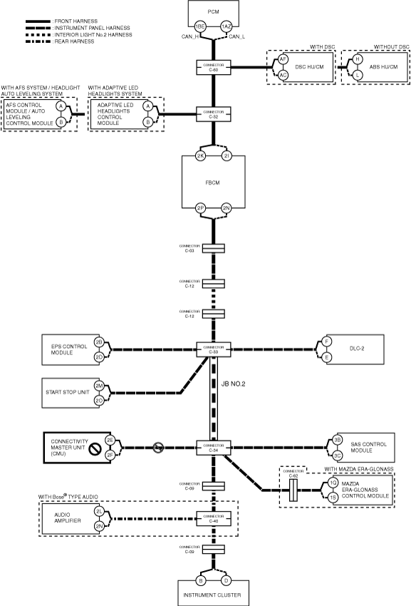
B
Possible cause
System wiring diagram
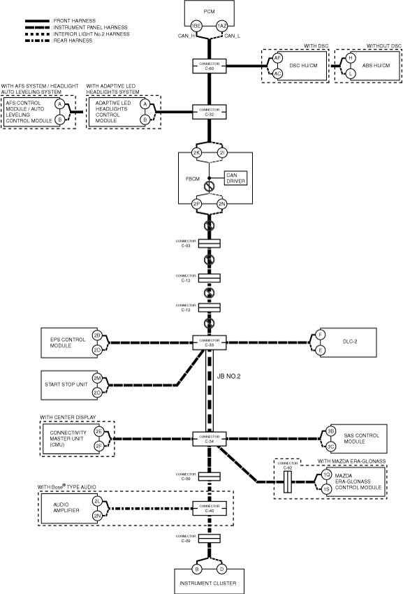
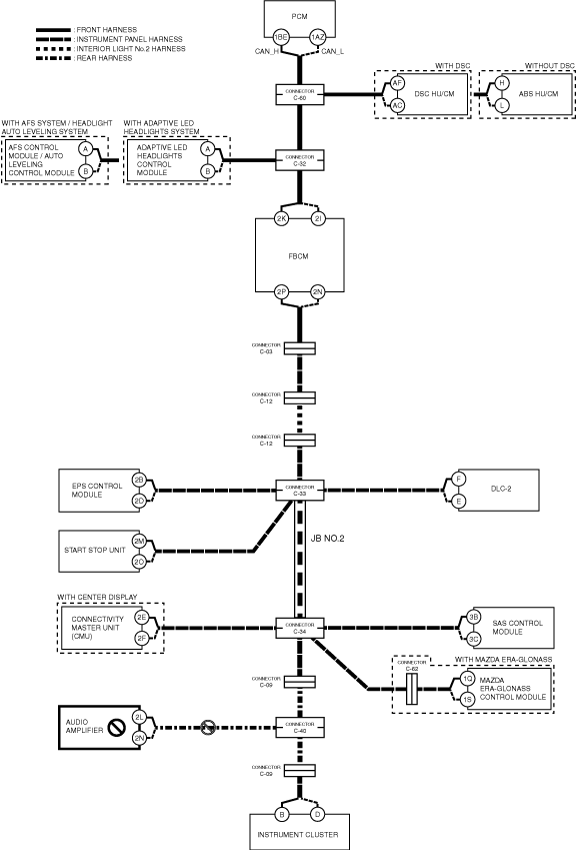
am3zzw00019450
|
Inspection item
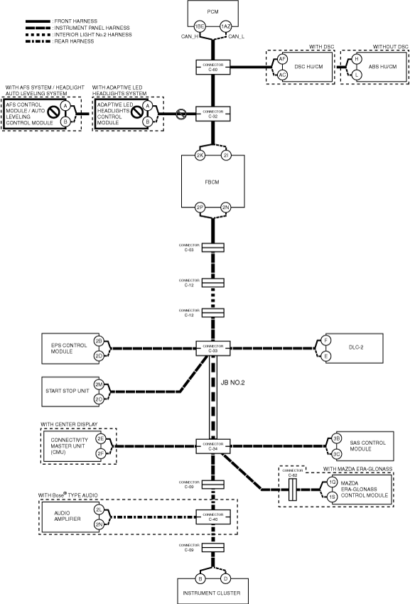
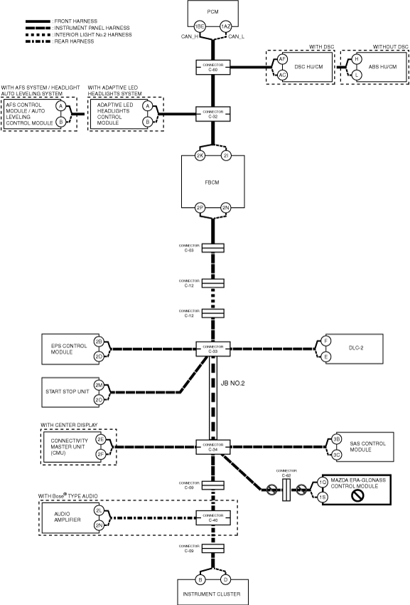
C
Possible cause
System wiring diagram
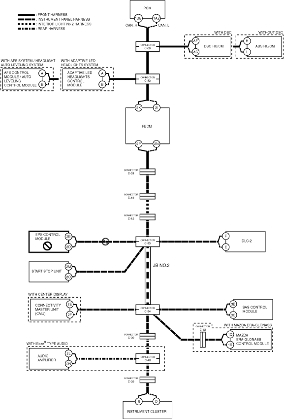
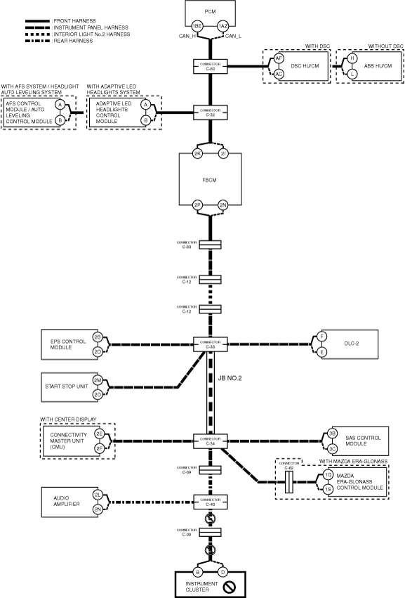
am3zzw00019451
|
Inspection item
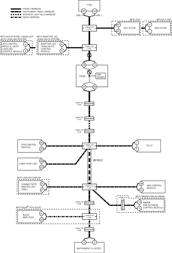
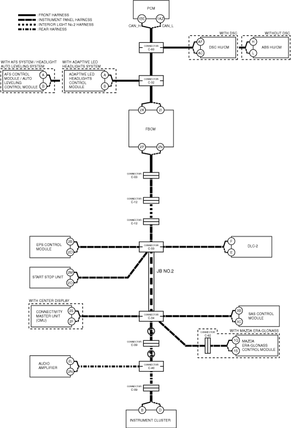
D
Possible cause
System wiring diagram
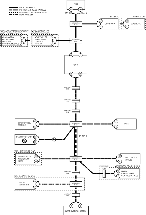
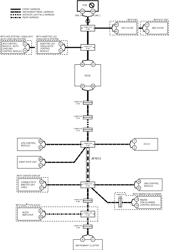
am3zzw00019452
|
Inspection item
E
Possible cause
System wiring diagram
am3zzw00019453
|
Inspection item
F
Possible cause
System wiring diagram
am3zzw00019454
|
Inspection item
G
Possible cause
System wiring diagram
am3zzw00019455
|
Inspection item
H
Possible cause
System wiring diagram
am3zzw00019456
|
Inspection item
I
Possible cause
System wiring diagram
am3zzw00019457
|
Inspection item
J
Possible cause
System wiring diagram
am3zzw00019458
|
Inspection item
K
Possible cause
System wiring diagram
am3zzw00019459
|
Inspection item
L
Possible cause
System wiring diagram
am3zzw00019460
|
Inspection item
M
Possible cause
System wiring diagram
am3zzw00020411
|
Inspection item
N
With Bose® type audio
System wiring diagram
am3zzw00019461
|
Without Bose® type audio
System wiring diagram
am3zzw00019462
|
O
Possible cause
System wiring diagram
am3zzw00019463
|
Inspection item
P
Possible cause
System wiring diagram
am3zzw00019464
|
Inspection item