|
beleue00000039
VALVE CLEARANCE ADJUSTMENT
id011000503600
1. Remove the engine front cover lower blind plug.
beleue00000039
|
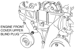
2. Remove the engine front cover upper blind plug.
belbze00000204
|
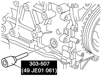
3. Remove the cylinder block lower blind plug, and install the SST.
Cylinder block lower blind plug hole diameter: M8
belbze00000201
|
Cylinder block lower blind plug hole diameter: M10
ampjjw00002884
|
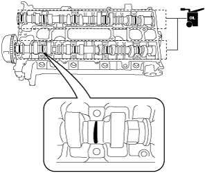
4. Rotate the crankshaft in the direction of the engine rotation so that the No.1 piston is at TDC of the compression stroke. (Until the counterweight contacts SST and stops.)
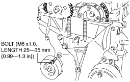
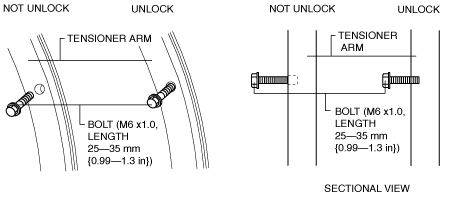
5. Loosen the timing chain using the following procedure:
beleue00000041
|
am8rrw00002539
|
belbze00000198
|
am8rrw00002541
|
beleue00000042
|
aprjjw00003610
|
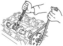
6. Fix the exhaust camshaft using a wrench on the cast hexagon, and loosen the camshaft sprocket bolt.
am3zzw00002423
|
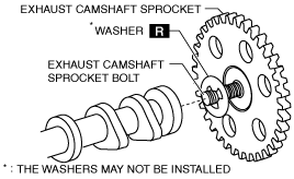
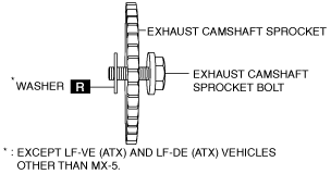
7. Remove the exhaust camshaft sprocket bolt, exhaust camshaft sprocket, and washer (The washers may not be installed.) as a single unit.
belbze00000210
|
8. Remove the oil control valve (OCV). (With variable valve timing mechanism.)
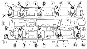
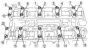
9. Loosen the camshaft cap bolts in two or three steps in the order shown in the figure and remove the camshaft cap.
am8rrw00000586
|
10. Remove the camshafts for the intake and exhaust sides.
11. Remove the tappet.
12. Install an appropriate tappet based on the results of the valve clearance inspection.
acmzzw00000071
|
Tappet specification
|
Identification mark
|
Thickness (mm {in})
|
Tolerance (mm {in})
|
|
000
|
3.000 {0.1181}
|
±0.0125 {0.000492}
|
|
025
|
3.025 {0.1191}
|
±0.0125 {0.000492}
|
|
050
|
3.050 {0.1201}
|
±0.0125 {0.000492}
|
|
075
|
3.075 {0.1211}
|
±0.0125 {0.000492}
|
|
100
|
3.100 {0.1220}
|
±0.0125 {0.000492}
|
|
122
|
3.122 {0.1229}
|
±0.0100 {0.000394}
|
|
142
|
3.142 {0.1237}
|
±0.0100 {0.000394}
|
|
162
|
3.162 {0.1245}
|
±0.0100 {0.000394}
|
|
182
|
3.182 {0.1253}
|
±0.0100 {0.000394}
|
|
202
|
3.202 {0.1261}
|
±0.0100 {0.000394}
|
|
222
|
3.222 {0.1269}
|
±0.0100 {0.000394}
|
|
242
|
3.242 {0.1276}
|
±0.0100 {0.000394}
|
|
262
|
3.262 {0.1284}
|
±0.0100 {0.000394}
|
|
282
|
3.282 {0.1292}
|
±0.0100 {0.000394}
|
|
302
|
3.302 {0.130}
|
±0.0100 {0.000394}
|
|
322
|
3.322 {0.1308}
|
±0.0100 {0.000394}
|
|
342
|
3.342 {0.1316}
|
±0.0100 {0.000394}
|
|
362
|
3.362 {0.1324}
|
±0.0100 {0.000394}
|
|
382
|
3.382 {0.1331}
|
±0.0100 {0.000394}
|
|
402
|
3.402 {0.1339}
|
±0.0100 {0.000394}
|
|
422
|
3.422 {0.1347}
|
±0.0100 {0.000394}
|
|
442
|
3.442 {0.1355}
|
±0.0100 {0.000394}
|
|
462
|
3.462 {0.1363}
|
±0.0100 {0.000394}
|
|
482
|
3.482 {0.1371}
|
±0.0100 {0.000394}
|
|
502
|
3.502 {0.1379}
|
±0.0100 {0.000394}
|
|
522
|
3.522 {0.1387}
|
±0.0100 {0.000394}
|
|
542
|
3.542 {0.1394}
|
±0.0100 {0.000394}
|
|
562
|
3.562 {0.1402}
|
±0.0100 {0.000394}
|
|
582
|
3.582 {0.1410}
|
±0.0100 {0.000394}
|
|
602
|
3.602 {0.1418}
|
±0.0100 {0.000394}
|
|
625
|
3.625 {0.1427}
|
±0.0125 {0.000492}
|
|
650
|
3.650 {0.1437}
|
±0.0125 {0.000492}
|
|
675
|
3.675 {0.1447}
|
±0.0125 {0.000492}
|
|
700
|
3.700 {0.1457}
|
±0.0125 {0.000492}
|
|
725
|
3.725 {0.1467}
|
±0.0125 {0.000492}
|
13. Verify that No.1 cylinder is at TDC of the compression stroke. (Position counterweight contacts SST.)
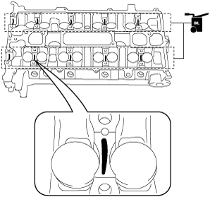
14. Apply the gear oil (SAE No.90 or equivalent) to each journal of the cylinder head as shown in the figure.
am6zzw00002188
|
15. Install the camshaft with No.1 cylinder aligned with the TDC position.
16. Apply the gear oil (SAE No.90 or equivalent) to each journal of the camshaft as shown in the figure.
am6zzw00002281
|
17. Temporarily tighten the camshaft cap bolts evenly in 2—3 steps.
18. Tighten the camshaft cap bolts in the order shown in the following two steps.
am8rrw00000587
|
19. Install the OCV. (With variable valve timing mechanism.)
20. Install the exhaust camshaft sprocket bolt, exhaust camshaft sprocket, and a new washer (Except LF-VE (ATX) and LF-DE (ATX) vehicles other than MX-5.) as a single unit.
belbze00000213
|
21. Install the SST on the camshaft as shown in the figure.
Europe
belbze00000134
|
Except Europe
belbze00000135
|
belbze00000172
|
22. Remove the installation bolt for the engine front cover upper blind plug (M6 X 1.0 length 25—35mm {1.0—1.3 in}), and apply tension to the timing chain.
23. Rotate the crankshaft clockwise and verify that the No.1 cylinder is at TDC of the compression stroke. (The position counter weight contacts the SST.)
24. Fix the exhaust camshaft using a wrench on the cast hexagon, and tighten the sprocket bolt.
am8rrw00002546
|
Tightening torque
|
Bolt type |
N·m {kgf·m, ft·lbf} |
|---|---|
|
Washer based bolt
|
With variable valve timing mechanism : 69—75 {7.1—7.6, 50.9—55.3}
Without variable valve timing mechanism : 89—95 {9.1—9.6, 65.7—70.0}
|
|
Bolt and washer assembly
|
69—75
{7.1—7.6, 50.9—55.3}
|
|
Bolt with dent on head
|
69—75
{7.1—7.6, 50.9—55.3}
|
25. Remove the SST from the camshaft.
26. Remove the SST installed in the cylinder block lower blind plug hole.
27. Rotate the crankshaft clockwise two turns and inspect the valve timing.
28. Apply the silicone sealant and install the engine front cover upper blind plug.
belbze00000205
|
29. Install the cylinder block lower blind plug.
am6zzw00000888
|
30. Install a new engine front cover lower blind plug.
beleue00000039
|