|
bem5ze00000097
CYLINDER BLOCK ASSEMBLY (II) [MZR-CD 2.2]
id0110f2504100
1. Assemble in the order indicated in the table.
bem5ze00000097
|
|
1
|
Oil pump body
|
|
2
|
Control plunger
|
|
3
|
Plunger spring
|
|
4
|
Plunger plug
|
|
5
|
Inner rotor and shaft component, outer rotor
|
|
6
|
Oil pump cover
|
|
7
|
Oil pump
(See Oil Pump Installation Note.)
|
|
8
|
Chain case
(See Chain case Installation Note.)
|
|
9
|
Oil pan upper block
|
|
10
|
Balancer complete
|
|
11
|
Balancer chain, balancer sprocket
|
|
12
|
Balancer chain guide*
|
|
13
|
Balancer chain tensioner arm
|
|
14
|
Balancer chain tensioner
|
|
15
|
Oil pan
(See Oil Pan Installation Note.)
|
|
16
|
Vacuum pump
|
|
17
|
Rear cover
(See Rear Cover Installation Note.)
|
|
18
|
End plate
|
|
19
|
Flywheel
(See Flywheel Installation Note.)
|
Inner Rotor And Shaft Component, Outer Rotor Assembly Note
1. Install the inner rotor and outer rotor so that their punch marks are oriented towards the oil pump cover.
am6zzw00004529
|
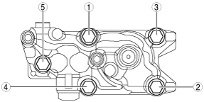
Oil Pump Installation Note
1. Tighten the oil pump installation bolts in the order shown in the figure.
bem5ze00000098
|
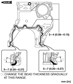
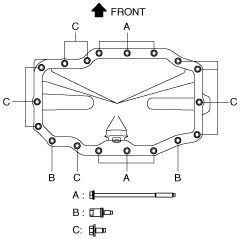
Chain case Installation Note
1. Apply sealant as shown in the figure.
bem5ze00000135
|
2. Tighten the bolts in the order shown in the figure.
bem5ze00000135
|
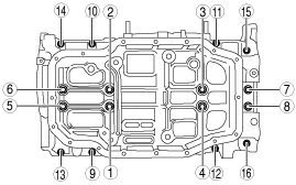
Oil Pan Upper Block Installation Note
1. Apply sealant as shown in the figure.
bem5ze00000139
|
2. Tighten the bolts in the order shown in the figure.
bem5ze00000130
|
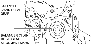
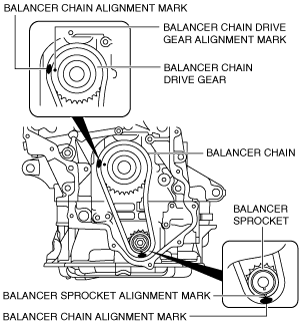
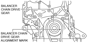
Balancer Chain, Balancer Sprocket Installation Note
1. Rotate the crankshaft until the balancer chain drive gear pin is in the positions shown in the figure. (No.2 piston is at TDC).
bem5ze00000147
|
2. Set the balancer chain to the balancer chain drive gear so that the balancer chain alignment mark (gold colored link) aligns with the balancer chain drive gear alignment mark.
bem5ze00000148
|
3. Install the balancer sprocket to the balancer chain so that the balancer sprocket alignment mark aligns with the balancer chain alignment mark (gold colored link).
4. Install the balancer sprocket to the balancer unit and temporarily install the balancer sprocket lock bolt.
5. Secure the balancer shaft using a wrench on the cast hexagon.
bem5ze00000128
|
6. Tighten the balancer sprocket lock bolt.
7. Rotate the crankshaft until the crankshaft sprocket alignment marks are in the positions shown in the figure. (No.1 piston is at TDC).
bem5ze00000150
|
Balancer Chain Tensioner Installation Note
1. Install the balancer chain tensioner.
2. Remove the hexagonal wrench which has been installed to secure the plunger.
Oil Pan Installation Note
am3zzw00003973
|
1. Completely clean and remove any oil, dirt, sealant or other foreign material that may be adhering to the oil pan upper block and oil pan.
2. When reusing the oil pan installation bolts, clean any old sealant from the bolts.
3. Apply silicone sealant to the oil pan along the inside of the bolt holes as shown in the figure.
bem5ze00000099
|
4. Install the oil pan to the oil pan upper block.
5. Install the oil pan installation bolts as shown in the figure.
bem5ze00000100
|
6. Tighten the oil pan installation bolts in the order shown in the figure.
am6zzw00004527
|
7. Tighten the remaining oil pan installation bolts.
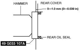
Rear Cover Installation Note
1. Apply clean engine oil to the oil seal lip.
2. Push the oil seal slightly in by hand.
3. Tap the oil seal in evenly using the SST and a hammer.
am6zzw00004187
|
4. Apply sealant as shown in the figure.
bem5ze00000131
|
5. Tighten the bolts in the order shown in the figure.
bem5ze00000132
|
Flywheel Installation Note
1. Clean the crankshaft thread holes.
2. Install the flywheel to the crankshaft.
3. When reusing the bolts, clean threads and hole, then apply locking compound to the threads.
4. Hand-tighten the new flywheel lock bolts.
5. Install the SST to the flywheel.
bem5ze00000103
|
6. Gradually tighten the flywheel lock bolts in a crisscross pattern.