 |
e6u316zmc100
TRANSFER DISASSEMBLY
d6e031627500102
Before Service Precautions
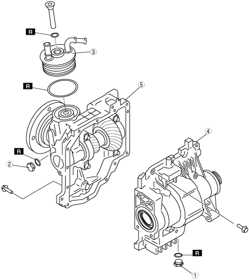
Transfer Component Disassembly
e6u316zmc100
|
|
1
|
Drain plug
|
|
2
|
Oil level plug
|
|
3
|
Oil cooler
|
|
4
|
Drive gear case component
|
|
5
|
Front carrier component
|
Transfer Component Disassembling Procedure
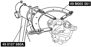
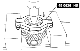
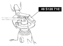
1. Assemble the SSTs.
e6u316zmc014
|
2. Install the transfer component to the SSTs.
e6u316zmc015
|
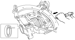
3. Remove the oil cooler.
4. Remove the drive gear case component.
Drive Gear Case Component Disassembly
e6u316zmc102
|
|
1
|
Oil seal (RH outer)
|
|
2
|
Drive gear shaft
|
|
3
|
Bearing cap
|
|
4
|
Adjustment shim
|
|
5
|
Spacer
|
|
6
|
Drive gear component
|
|
7
|
Bearing outer race (LH)
|
|
8
|
Bearing outer race (RH)
|
|
9
|
Bearing (RH)
|
|
10
|
Bearing (LH)
|
|
11
|
Drive gear
|
|
12
|
Oil seal (RH inner)
|
|
13
|
Oil seal (LH)
|
|
14
|
Baffle plate
|
|
15
|
Drive gear case
|
Drive Gear Case Component Disassembly Procedure
1. Install the drive gear case component to the SST.
e6u316zmc001
|
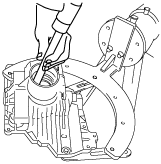
2. Tap the drive gear shaft using a suittable rod and hammer.
e6u316zmc065
|
3. Take out the drive gear shaft from the drive gear case.
e6u316zmc004
|
4. Make alignment marks on the bearing cap and drive gear case.
e6u316zmc005
|
5. Remove the bearing cap.
6. Insert a flathead screwdriver into spacer notch and remove the adjustment shim.
e6u316zmc006
|
e6u316zmc007
|
7. Remove the spacer.
e6u316zmc008
|
8. Remove the drive gear component.
e6u316zmc009
|
9. Insert a flathead screwdriver in the direction of the arrow and tap the oil seal (LH) to remove it.
e6u316zmc201
|
10. Using a tape-wrapped pliers, remove the oil seal (RH outer).
e6u316zmc202
|
11. Insert a flathead screwdriver in the direction of the arrow and tap the oil seal (RH inner) to remove it.
e6u316zmc203
|
12. Using the SST, remove the bearing outer race (LH).
e6u316zmc010
|
e6u316zmc109
|
e6u316zmc018
|
13. Remove the baffle plate.
e6u316zmc107
|
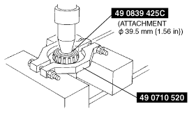
14. Using the SST, remove the bearing (RH).
e6u316zmc021
|
15. Using a flathead screwdriver, deform the bearing roller guide (LH) and remove it.
e6u316zmc019
|
16. Using the SST, remove the bearing inner race (LH).
e6u316zmc020
|
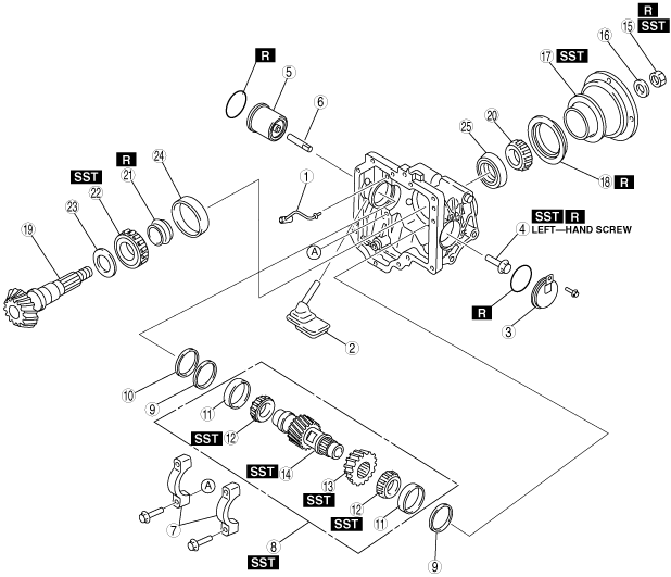
Front Carrier Component Disassembly
e6u316zmc103
|
|
1
|
Oil pipe
|
|
2
|
Oil strainer
|
|
3
|
Side cover
|
|
4
|
Ring gear lockbolt
|
|
5
|
Oil pump
|
|
6
|
Oil pump shaft
|
|
7
|
Bearing cap
|
|
8
|
Ring gear component
|
|
9
|
Adjustment shim
|
|
10
|
Spacer
|
|
11
|
Bearing outer race (side)
|
|
12
|
Bearing (side)
|
|
13
|
Ring gear
|
|
14
|
Ring gear shaft
|
|
15
|
Locknut
|
|
16
|
Washer
|
|
17
|
Companion flange
|
|
18
|
Oil seal
|
|
19
|
Drive pinion gear
|
|
20
|
Bearing (rear)
|
|
21
|
Distance piece
|
|
22
|
Bearing (front)
|
|
23
|
Spacer
|
|
24
|
Bearing outer race (front)
|
|
25
|
Bearing outer race (rear)
|
Front Carrier Component Disassembling Procedure
1. Install the front carrier component to the SST.
e6u316zmc022
|
2. Remove the oil strainer.
3. Remove the oil pipe.
4. Remove the side cover.
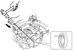
5. Remove the oil pump by turning it using pliers as shown in the figure.
e6u316zmc024
|
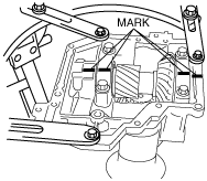
6. Make alignment marks on the bearing caps and front carrier.
e6u316zmc112
|
7. Remove the bearing caps.
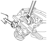
8. Using a suitable wrench, secure the ring gear shaft, and remove the ring gear lockbolt.
e6u316zmc023
|
9. Using the SST, secure the companion flange, and remove the locknut and washer.
buj0517a349
|
10. Using the SST, remove the companion flange.
buj0517a350
|
11. Using the SSTs, remove the ring gear component.
e6u316zmc026
|
12. Remove the adjustment shims and spacer.
13. Install an appropriate nut to the drive pinion to prevent the thread from being damaged.
buj0517a353
|
14. Lightly tap the drive pinion using a copper hammer and remove the drive pinion gear.
15. Using a flathead screwdriver, remove the oil seal.
e6u316zmc027
|
16. Remove the bearing (rear) and distance piece.
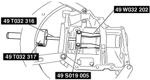
17. Using the SST, remove the bearing (front).
e6u316zmc028
|
18. Remove the spacer.
19. Attach the brass stick to the notch, tap the race end lightly and evenly, then remove the bearing outer races.
e6u316zmc029
|
e6u316zmc030
|
20. Using the SSTs, remove the bearing (side) (opposite ring gear side).
e6u316zmc114
|
21. Using a SST, remove the bearing (side) (ring gear side) together with ring gear.
e6u316zmc031
|