TRANSFER ASSEMBLY
D6E031627500103
Before Service Precautions
• Assemble with bare hands or using vinyl gloves. To prevent foreign material from entering the transfer, do not use cotton work gloves or a rag.
• Apply sufficient gear oil to the sliding surfaces and O-rings, and be careful not to damage when assembling.
• Replace the transfer with a new one if the case alignment surface is damaged. Be careful not to damage it since it may cause oil leakage.
• When installing silicone sealant, clean off the old sealant adhering to the sealing area and clean the sealing area with cleaning fluids.
• After installing a seal, leave the parts alone for 2 h or more. Do not add oil or operate the vehicle during this time.
-
Warning
-
• The engine stand is equipped with a self-lock mechanism. However, if the transfer is tilted, the self-lock mechanism could become inoperative. This could cause the transfer to rotate accidentally, resulting in injury. Therefore, make sure that the transfer is not tilted when it is on the engine stand. When turning the transfer, grasp the rotation handle firmly.
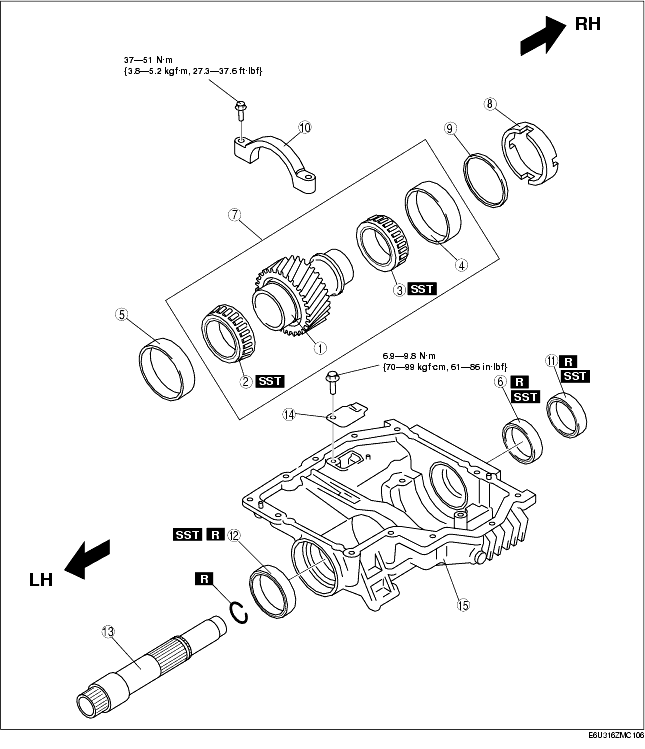
Drive Gear Case Component Assembly
.
|
1
|
Drive gear
|
|
2
|
Bearing (LH)
|
|
3
|
Bearing (RH)
|
|
4
|
Bearing outer race (RH)
|
|
5
|
Bearing outer race (LH)
|
|
6
|
Oil seal (RH inner)
|
|
7
|
Drive gear component
|
|
8
|
Spacer
|
|
9
|
Adjustment shim
|
|
10
|
Bearing cap
|
|
11
|
Oil seal (RH outer)
|
|
12
|
Oil seal (LH)
|
|
13
|
Drive gear shaft
|
|
14
|
Baffle plate
|
|
15
|
Drive gear case
|
Drive Gear Case Component Assembly Procedure
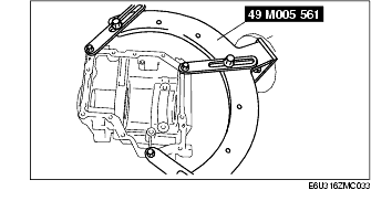
1. Install the drive gear case to the SST.
2. Install the baffle plate.
Tightening torque
-
6.9-9.8 N·m {70-99 kgf·cm, 61-86 in·lbf}
3. Using a press, assemble the bearing (RH).
4. Using a press, assemble the bearing (LH).
5. Temporarily assemble the bearing outer race (RH) and spacer to the drive gear.
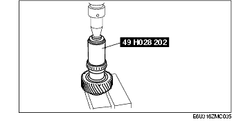
6. Place the drive gear component on the surface plate as shown in the figure, and measure the height using a vernier caliper or height gauge. This is dimension A.
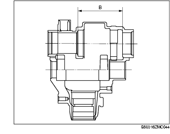
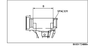
7. Measure the width of the drive gear installation area in the drive gear case. This is dimension B.
8. The maximum and minimum thickness C of the adjustment shim can be expressed by the following formula:
-
C = B - A - (0.01-0.03 mm {0.00039-0.00118 in})
9. If the thickness of the installed adjustment shim is within the C range, use the shim as it is.
10. If the thickness of the installed adjustment shim is not within the C range, select the appropriate adjustment shim from the table below and use it.
Adjustment shim
|
Identification mark
|
Thickness (mm {in})
|
Identification mark
|
Thickness (mm {in})
|
|
350
|
3.50 {0.1378}
|
420
|
4.20 {0.1654}
|
|
355
|
3.55 {0.1398}
|
425
|
4.25 {0.1673}
|
|
360
|
3.60 {0.1417}
|
430
|
4.30 {0.1693}
|
|
365
|
3.65 {0.1437}
|
435
|
4.35 {0.1713}
|
|
370
|
3.70 {0.1457}
|
440
|
4.40 {0.1732}
|
|
375
|
3.75 {0.1476}
|
445
|
4.45 {0. 1752}
|
|
380
|
3.80 {0.1496}
|
450
|
4.50 {0.1772}
|
|
385
|
3.85 {0.1516}
|
455
|
4.55 {0.1791}
|
|
390
|
3.90 {0.1535}
|
460
|
4.60 {0. 1811}
|
|
395
|
3.95 {0.1555}
|
-
|
-
|
|
400
|
4.00 {0.1575}
|
-
|
-
|
|
405
|
4.05 {0.1594}
|
-
|
-
|
|
410
|
4.10 {0.1614}
|
-
|
-
|
|
415
|
4.15 {0.1634}
|
-
|
-
|
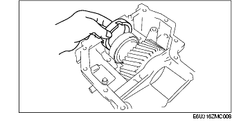
11. Using the plastic hammer, install the bearing outer race (LH).
12. Install the drive gear component.
13. Install the spacer with its notch facing the bearing, and also facing upward, as shown in the figure.
14. Using a plastic hammer, assemble the adjustment shim.
15. Align the bearing cap alignment marks, assemble the bearing cap.
Tightening torque
-
37-51 N·m {3.8-5.2 kgf·m, 27.3-37.6 ft·lbf}
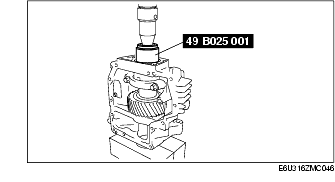
16. Assemble the SST to the drive gear shaft, and hand-tighten the nut.
SST tightening torque
-
2.1 N·m {21 kgf·cm, 19 in·lbf}
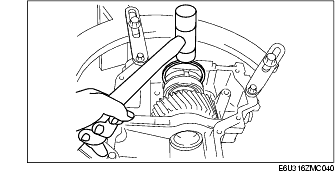
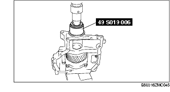
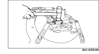
17. Install the drive gear shaft with the SST assembled and verify that the preload is within the specification using the torque wrench as shown in the figure.
Standard drive gear bearing preload
-
0.6-2.1 N·m {6.2-21.4 kgf·cm, 5.4-18.5 in·lbf}
-
• If the drive gear rotational torque is not within the specification, adjust it by selecting the proper spacer.
18. Remove the drive gear shaft.
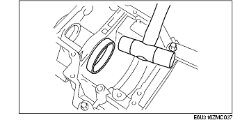
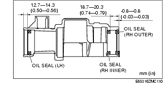
19. Using a press, install the oil seals.
-
Note
-
• Mark the press-in depth of each oil seal to the SST and press fit oil seals to the specified position.
Oil seal installation lengths
LH
RH inner
RH outer
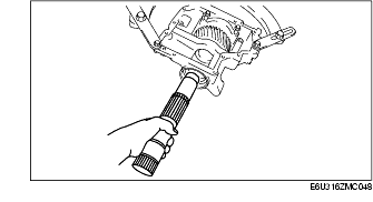
20. Install the C-ring to the drive gear shaft and insert the drive gear shaft until it is secured by the C-ring.
-
Caution
-
• Be careful not to damage the oil seal when installing the drive gear shaft.
21. Pull the drive gear shaft by hand and verify that the drive gear shaft is secured by the C-ring at the specified position.
Front Carrier Component Assembly

|
1
|
Bearing outer race (rear)
|
|
2
|
Bearing outer race (front)
|
|
3
|
Spacer
|
|
4
|
Bearing (front)
|
|
5
|
Distance piece
|
|
6
|
Bearing (rear)
|
|
7
|
Drive pinion gear
|
|
8
|
Oil seal
|
|
9
|
Companion flange
|
|
10
|
Washer
|
|
11
|
Locknut
|
|
12
|
Ring gear shaft
|
|
13
|
Ring gear
|
|
14
|
Bearing (side)
|
|
15
|
Bearing outer race (side)
|
|
16
|
Adjustment shim
|
|
17
|
Spacer
|
|
18
|
Ring gear component
|
|
19
|
Bearing cap
|
|
20
|
Oil pump shaft
|
|
21
|
Oil pump
|
|
22
|
Ring gear lockbolt
|
|
23
|
Side cover
|
|
24
|
Oil strainer
|
|
25
|
Oil pipe
|
Front Carrier Component Assembly Procedure
1. Using a press, assemble the opposite ring gear side bearing (side) to the ring gear shaft.
2. Using a press, assemble the ring gear to the ring gear shaft
3. Using a press, assemble the ring gear side bearing (side).
4. Temporarily assemble the bearing outer races (side).
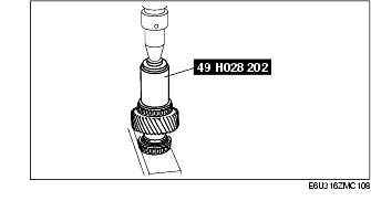
5. Place the ring gear component on the surface plate as shown in the figure, and measure the height using a vernier caliper or height gauge. This is dimension A.
6. Measure the width of the front carrier ring gear installation area with the spacer installed. This is dimension B.
7. The maximum and minimum total thickness C of the adjustment shims on both sides can be expressed by the following formula:
-
C = B - A - (0.01-0.03 mm {0.00039-0.00118 in})
8. If the total thickness of the installed adjustment shims is within the C range, use the shims as they are.
9. If the total thickness of the installed adjustment shims is not within the C range, select the appropriate number of adjustment shims from the table below and use them.
Adjustment shim
|
Identification mark
|
Thickness (mm {in})
|
Identification mark
|
Thickness (mm {in})
|
|
350
|
3.50 {0.1378}
|
410
|
4.10 {0.1614}
|
|
355
|
3.55 {0.1398}
|
415
|
4.15 {0.1634}
|
|
360
|
3.60 {0.1417}
|
420
|
4.20 {0.1654}
|
|
365
|
3.65 {0.1437}
|
425
|
4.25 {0.1673}
|
|
370
|
3.70 {0.1457}
|
430
|
4.30 {0.1693}
|
|
375
|
3.75 {0.1476}
|
435
|
4.35 {0.1713}
|
|
380
|
3.80 {0.1496}
|
440
|
4.40 {0.1732}
|
|
385
|
3.85 {0.1516}
|
445
|
4.45 {0.1752}
|
|
390
|
3.90 {0.1535}
|
450
|
4.50 {0.1772}
|
|
395
|
3.95 {0.1555}
|
455
|
4.55 {0.1791}
|
|
400
|
4.00 {0.1574}
|
460
|
4.60 {0.1811}
|
|
405
|
4.05 {0.1594}
|
-
|
-
|
-
Note
-
• When reusing adjustment shims, do not mix up the left and right shims.
-
• Do not mix up the left and right side bearing races and spacers.
10. Install the front carrier to the SST.
11. Install the adjustment shim chosen for the front carrier ring gear side and spacer on opposite side.
12. Assemble the ring gear component to the front carrier.
13. Using the plastic hammer, assemble the selected adjustment shim in between the spacer and bearing race as shown in the figure.
14. Align the alignment marks of the bearing caps, assemble the bearing caps, and tighten the bolts temporarily.
-
Caution
-
• Locking compound is applied to a new ring gear lockbolt. Reuse the old ring gear lock bolt when inspecting the preload.
15. Install the ring gear lockbolt and inspect the ring gear bearing preload.
Standard ring gear bearing preload
-
0.6-2.1 N·m {6.2-21.4 kgf·cm, 5.4-18.5 in·lbf}
-
• If the rotational torque is not within the specification, select the suitable adjustment shim and reinstall so that the rotational torque is within the specification.
16. Follow the disassembling procedure in Step 11 to remove the ring gear component.
-
Note
-
• Identify the left and right side of the adjustment shim for reinstallation.
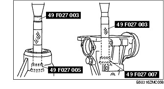
17. Using the SSTs, assemble the bearing outer races.
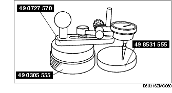
18. Using the SSTs, adjust the drive pinion height as follows:

-
(1) Install the SSTs to the removed spacer and bearing.
-
(2) Assemble the spacer, bearing and SSTs. Using an O-ring, secure the SST.
-
(3) Assemble the bearing, SSTs, washer, and nut.
-
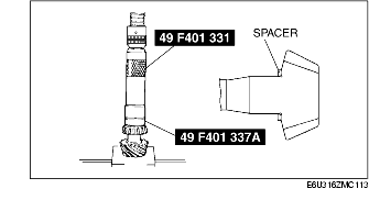
(4) Tighten the nut to the SST to where it can still be rotated by hand.
-
(5) Place the SSTs on the plate surface and set the dial gauge to "0".
-
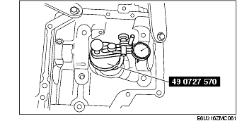
(6) Position the SST (49 0727 570) on the driver pinion model.
-
(7) Attach the dial gauge head to where the carrier bearing outer race (side) is installed and measure the lowest position. Also, measure the value of where the side bearing outer race (side) is installed on the opposite side.
-
(8) Measure the average value between the values of both sides measured in Step 7. This value is the spacer thickness which determines the pinion height.
Pinion height error factor within allowance limit
-
± 0.032 mm {± 0.00126 in}
Spacer
|
Identification mark
|
Thickness (mm {in})
|
Identification mark
|
Thickness (mm {in})
|
|
08
|
3.08 {0.1213}
|
29
|
3.29 {0.1295}
|
|
09
|
3.095 {0.1219}
|
30
|
3.305 {0.1301}
|
|
11
|
3.11 {0.1224}
|
32
|
3.32 {0.1307}
|
|
12
|
3.125 {0.1230}
|
33
|
3.335 {0.1313}
|
|
14
|
3.14 {0.1236}
|
35
|
3.35 {0.1319}
|
|
15
|
3.155 {0.1242}
|
36
|
3.365 {0.1325}
|
|
17
|
3.17 {0.1248}
|
38
|
3.38 {0.1331}
|
|
18
|
3.185 {0.1254}
|
39
|
3.395 {0.1335}
|
|
20
|
3.20 {0.1260}
|
41
|
3.41 {0.1343}
|
|
21
|
3.215 {0.1266}
|
42
|
3.425 {0.1348}
|
|
23
|
3.23 {0.1272}
|
44
|
3.44 {0.1354}
|
|
24
|
3.245 {0.1278}
|
45
|
3.455 {0.1360}
|
|
26
|
3.26 {0.1283}
|
47
|
3.47 {0.1366}
|
|
27
|
3.275 {0.1289}
|
-
|
-
|
19. Assemble the spacer selected for pinion height adjustment with the rounded off side facing the gears.
20. Using the SST, assemble the bearing (front) to the drive pinion gear.
21. Assemble a new distance piece to the drive pinion gear.
22. Assemble the drive pinion gear to the front carrier.
23. Install the bearing (rear), companion flange, washer, and new locknut to the drive pinion and temporarily tighten.
24. Rotate the companion flange by hand and seat the bearing.
25. Using the SST, tighten the locknut from the lower limit of the specified tightening torque and set to the preload value. Note the tightening torque when the specified preload value is obtained.
-
Tightening torque
-
127-284 N·m {13.0-28.9 kgf·m, 93.7-209.4 ft·lbf}
-
Drive pinion preload value
-
0.88-1.37 N·m {9.0-14.0 kgf·cm, 7.9-12.1 in·lbf}
26. Remove the locknut, washer, and companion flange.
27. Apply oil to the lip area of a new oil seal.
28. Using the SST, assemble the oil seal.
29. Apply the grease to the bearing contact surface of the companion flange.
30. Assemble the companion flange.
31. Using the SST, tighten the new locknut to the tightening torque noted when the preload was adjusted.
32. Reverify the preload.
-
Drive pinion preload value
-
0.88-1.37 N·m {9.0-14.0 kgf·cm, 7.9-12.1 in·lbf}
33. Assemble the ring gear component following the procedure in Step 11 to 14.
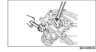
34. Set the dial gauge with the measuring probe attached perpendicularly to the end of one of the ring gear teeth.
35. Secure the drive pinion and measure the backlash from when the ring gear is moved.
-
Standard drive pinion backlash
-
0.09-0.11 mm {0.0035-0.0043 in}
-
Caution
-
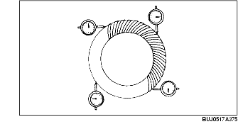
• Perform the backlash measurement on the ring gear circumference at four points.
36. If the backlash is not within the specified range above, adjust it by sliding the ring gear in the shaft direction.
-
Note
-
• Slide the ring gear in the shaft direction by replacing the adjustment shim. If the right side adjustment shim is replaced with one that is 0.05 mm {0.002 in} thicker, the left side shim must be replaced with one that is 0.05 mm {0.002 in} thinner.
37. Tighten the bearing cap bolts.
-
Tightening torque
-
63-93 N·m {6.5-9.4 kgf·m, 46.4-68.5 ft·lbf}
38. Perform the drive pinion and ring gear tooth contact inspection.
-
(1) Apply tooth marking compound evenly to both surfaces of the ring gear.
-
(2) Rotate the ring gear back and forth several times.
-
(3) Inspect for gear tooth contact at four points on the ring gear circumference and verify that the gear tooth contact indicated by the tooth marking compound is as indicated in the figure.
-
• If the tooth contact points are normal, wipe off the marking compound.
-
• If the tooth contact points are not normal, adjust the pinion height, then adjust the backlash.
-
(4) If toe and flank contact is indicated as shown in the figure, replace the drive pinion spacer with a thinner one to maintain the drive pinion further away.

-
(5) If heal and face contact is indicated as shown in the figure, replace the drive pinion spacer with a thicker one to bring the drive pinion closer.

39. Using a suitable wrench, secure the ring gear shaft and tighten the new ring gear lockbolt to the specified tightening torque.
-
Caution
-
• Before installing the new ring gear lockbolt, remove the old thread-locking compound remaining on the thread of the ring gear shaft.
-
Tightening torque
-
150-200 N·m {15.3-20.3 kgf·m, 110.7-147.4 ft·lbf}
40. Align the cast hexagon of the oil pump shaft and assemble the oil pump and oil pump shaft.
41. Align the oil holes of the oil pump and front carrier.
42. Assemble the oil strainer.
43. Assemble the oil pipe.
44. Apply oil to a new O-ring and assemble the side cover.
45. Assemble the side cover to the front carrier.
-
Tightening torque
-
6.9-9.8 N·m {70-100 kgf·cm, 61-86 in·lbf}
46. Remove the front carrier component from the SST.
Transfer Component Assembly

.
|
1
|
Front carrier component
|
|
2
|
Drive gear case component
|
|
3
|
Oil cooler
|
|
4
|
Drain plug
|
|
5
|
Oil level plug
|
Transfer Component Assembly Procedure
-
Note
-
• Before applying silicone sealant, completely clean off any old silicone sealant and remove any oil or grease.
-
• After applying silicone sealant, install the drive gear case within 10 min.
-
• After connecting the sealing area, leave it for 30 min. or more, then add transfer oil.
1. Clean the alignment surface of the front carrier and drive gear case, and lightly apply silicone sealant.
2. Assemble the transfer component.
Tightening torque
-
19-27 N·m {2.0-2.7 kgf·m, 14.1-19.9 ft·lbf}
3. Install the oil cooler.
4. Tighten the oil cooler installation bolt with a O-ring.
Tightening torque
-
23.5-29.4 N·m {2.4-2.9 kgf·m, 17.4-21.6 ft·lbf}
5. Tighten the drain plug with a new washer.
Tightening torque
-
39.2-58.8 N·m {4.0-5.9 kgf·m, 29.0-43.3 ft·lbf}