 |
bmgezm00000066
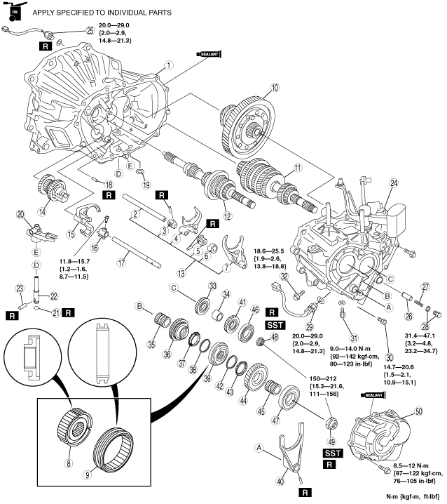
5TH/6TH GEAR AND HOUSING PARTS ASSEMBLY [TYPE A]
id051500810412
1. Assemble in the order indicated in the table.
bmgezm00000066
|
|
1
|
Clutch housing
(See Clutch Housing Assembly Note.)
|
|
2
|
Control rod
|
|
3
|
Control end
|
|
4
|
1st/2nd shift fork
|
|
5
|
Control lever
|
|
6
|
Interlock lever
|
|
7
|
3rd/4th shift fork
|
|
8
|
Clutch hub
|
|
9
|
Clutch hub sleeve
|
|
10
|
Differential component
|
|
11
|
Secondary shaft gear component
|
|
12
|
Primary shaft gear component
|
|
13
|
Shift fork and shift rod component
|
|
14
|
Reverse idler gear component
|
|
15
|
Reverse shift fork
|
|
16
|
5th/reverse shift rod end
|
|
17
|
5th/reverse shift rod
|
|
18
|
Roll pin
|
|
19
|
Magnet
|
|
20
|
Crank lever component
|
|
21
|
O-ring
|
|
22
|
Crank lever shaft
|
|
23
|
Pin
|
|
24
|
Transaxle case component
|
|
25
|
Neutral switch
|
|
26
|
Push pin component
|
|
27
|
Spring
|
|
28
|
Bolt and washer
|
|
29
|
Back-up light switch
|
|
30
|
Lock bolt
|
|
31
|
Guide bolt
|
|
32
|
Lock bolt
|
|
33
|
Secondary 5th gear
|
|
34
|
Spacer
|
|
35
|
Gear sleeve
|
|
36
|
5th gear
|
|
37
|
5th synchronizer ring
|
|
38
|
Synchronizer key spring
|
|
39
|
5th/6th clutch hub component
|
|
40
|
5th/6th shift fork
|
|
41
|
Secondary 6th gear
|
|
42
|
Synchronizer key spring
|
|
43
|
6th synchronizer ring
|
|
44
|
6th gear
|
|
45
|
Gear sleeve
|
|
46
|
Bearing (secondary shaft)
|
|
47
|
Bearing (primary shaft)
|
|
48
|
Locknut (secondary shaft)
|
|
49
|
Locknut (primary shaft)
|
|
50
|
Rear cover
|
Clutch Housing Assembly Note
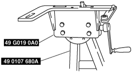
1. Assemble the SST.
bmgezm00000023
|
2. Assemble the clutch housing on the SST.
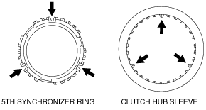
Clutch Hub and Clutch Hub Sleeve Assembly Note
1. Align the teeth of the clutch hub sleeve with the clutch hub grooves as shown in the figure, and assemble the clutch hub to the clutch hub sleeve.
bmgezm00000067
|
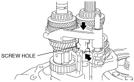
Secondary Shaft Gear Component, Primary Shaft Gear Component and Shift Fork and Shift Rod Component Assembly Note
1. Install the shift fork and shift rod component, primary shaft gear component and secondary shaft gear component at the same time.
bmgezm00000025
|
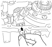
2. Press the control rod end edge to the back of the scraper and press the push pin component into the inner shift lever.
bmgezm00000026
|
3. Assemble the shift rod to the clutch housing by tapping the shift rod with a plastic hammer.
bmgezm00000027
|
4. Pull out the scraper.
5. Rotate the control end so that the push pin component is positioned at the center of the control end.
bmgezm00000028
|
Reverse Idler Gear Component, Reverse Shift Fork and 5th/Reverse Shift Rod End Assembly Note
1. Shift the 3rd/4th shift fork to 4th.
bmgezm00000029
|
2. Place the reverse idle gear component to the position shown in the figure.
bmgezm00000030
|
3. Assemble the reverse shift fork to the reverse idle gear component, and point the reverse idle gear component thread hole outward.
bmgezm00000031
|
4. After assembling the reverse shift fork, verify that the interlock sleeve end and control lever end are aligned as shown in the figure, and the reverse shift fork is engaged with interlock sleeve.
bmgezm00000032
|
5. Point the 5th/reverse shift rod end bolt hole and projection outward as shown in the figure, and place the 5th/reverse shift rod end on the reverse shift fork through the 3rd/4th shift fork.
bmgezm00000033
|
6. Assemble the 5th/reverse shift rod and tighten the bolts.
bmgezm00000034
|
Crank Lever Component and Crank Lever Shaft Assembly Note
1. Assemble the crank lever component to the change arm and control end.
2. Apply the specified oil to a new O-ring and install the O-ring to the crank lever shaft.
3. Assemble the crank lever shaft to the crank lever component.
bmgezm00000035
|
4. Using a flathead screwdriver, rotate the crank lever shaft so that the pin holes of the clutch housing and crank lever shaft are aligned, and then tap in a new spring pin using a hammer.
bmgezm00000036
|
Transaxle Case Component Assembly Note
1. Apply a thin coat of sealant to the contact surfaces of the clutch housing and transaxle case, and tighten the transaxle case installation bolts to the specified torque.
2. Install the SST through the drive shaft and joint shaft hole.
bmgezm00000037
|
Secondary 5th Gear Assembly Note
1. Install the secondary 5th gear as shown in the figure.
bmgezm00000038
|
5th/6th Clutch Hub Component and 5th/6th Shift Fork Assembly Note
1. Install the 5th/6th clutch hub component and the 5th/6th shift fork together.
bmgezm00000039
|
2. Align the teeth of the clutch hub sleeve with the 5th synchronizer ring grooves as shown in the figure, and assemble the clutch hub component.
bmgezm00000068
|
Secondary 6th Gear Assembly Note
1. Install the secondary 6th gear as shown in the figure.
bmgezm00000040
|
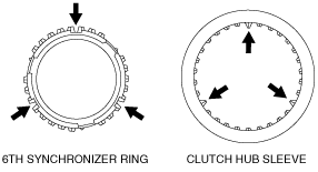
6th Synchronizer Ring Assembly Note
1. Align the teeth of the clutch hub sleeve with the 6th synchronizer ring grooves as shown in the figure, and assemble the 6th synchronizer ring.
bmgezm00000069
|
Bearing and Locknut Assembly Note
1. Shift to 1st gear.
2. Install the bearing.
3. Lock the primary shaft using the SST.
bmgezm00000041
|
4. Tighten the new lock nuts with the bearing onto the primary and secondary shafts.
5. Stake the locknuts.
6. Measure the 5th gear thrust clearance using a feeler gauge.
bmgezm00000042
|
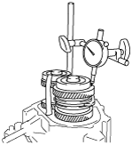
7. Measure the 6th gear thrust clearance using a dial indicator.
bmgezm00000043
|