1. Disassemble in the order indicated in the table.
2. Neatly arrange the removed parts to avoid confusing the similar parts.
3. Clean the removed parts with cleaning solvent, then use compressed air to dry them. Use compressed air to clean out all holes and passages.
1. Remove the oil strainer.
2. Remove the O-ring from the oil strainer.
3. Remove the packing.
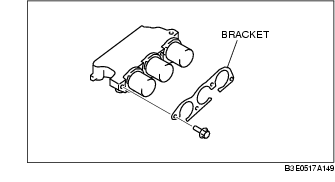
4. Remove the bracket.
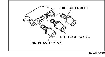
5. Remove the shift solenoid A, B, C.
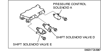
6. Remove the pressure control solenoid A, shift solenoid D, E.
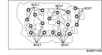
7. Loosen the bolts evenly in the pattern shown.
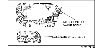
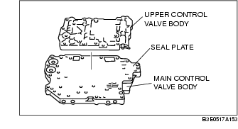
8. Remove the upper control valve body.
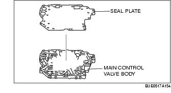
9. Remove the seal plate.
10. Remove the main control valve body.
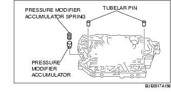
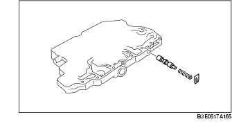
11. Remove the tubular pins, pressure modifier accumulator spring and pressure modifier accumulator from the main control valve body.
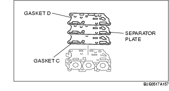
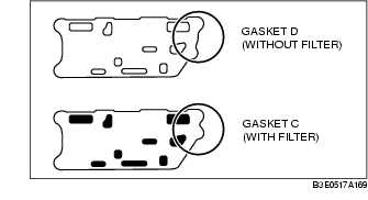
12. Remove the gasket D, separator plate and gasket C.
13. Remove the tubular pins.
1. Disassemble in the order indicated in the table.
2. Clean all parts and holes using compressed air and apply ATF to them immediately before assembly.
3. Assemble in the reverse order of disassembly.
|
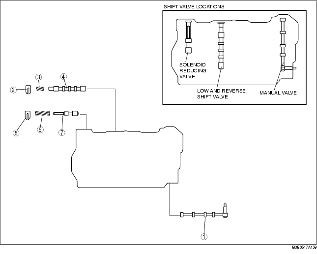
1
|
Manual valve
|
|
2
|
Retainer
|
|
3
|
Low and reverse shift valve spring
|
|
4
|
Low and reverse shift valve
|
|
5
|
Retainer
|
|
6
|
Solenoid reducing valve spring
|
|
7
|
Solenoid reducing valve
|
1. Measure the spring free length.
Primary control valve body spring (standard)
2. Install the solenoid reducing valve, solenoid reducing valve spring and retainer.
3. Install the low and reverse shift valve, low and reverse shift valve spring and retainer.
4. Install the manual valve.
1. Disassemble in the order indicated in the table.
2. Clean all parts and holes using compressed air and apply ATF to them immediately before assembly.
3. Assemble in the reverse order of disassembly.

1. Measure the spring free length.
Primary control valve body spring (standard)
2. Install the 3-4 shift valve, 3-4 shift valve spring, and retainer.
3. Install the bypass valve, bypass valve spring, and retainer.
4. Install the torque converter clutch control valve, torque converter clutch control valve spring, and retainer.
5. Install the converter relief valve, converter relief valve spring, and retainer.
6. Install the solenoid shift valve, solenoid shift valve spring, and retainer.
7. Install the pressure regulator valve, pressure regulator valve spring, and retainer.
1. Verify that all parts are clean and free of dust and other small particles.
2. Apply ATF to all parts.
3. Assemble in the reverse order of disassembly.

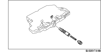
1. Install the tubular pins into the solenoid control valve body.
2. Set the new gasket C, separator plate, and new gasket D on the solenoid control valve body.
3. Install the pressure modifier accumulator and pressure modifier accumulator spring into the main control valve body.
Primary control valve body spring (standard)
|
Item
|
Outer diameter
mm {in}
|
Free length
mm {in}
|
No. of coils
|
Wire diameter
mm {in}
|
|---|---|---|---|---|
|
Pressure modifier accumulator spring
|
11.0 {0.433}
|
23.0 {0.906}
|
6.6
|
1.5 {0.059}
|
4. Install the tubular pins into the main control valve body.
5. Set the main control valve body onto the solenoid control valve body.
6. Set the seal plate on the main control valve body.
7. Set the upper control valve body onto the main control valve body.
8. Hand-tighten the bolts shown in the figure. Each type of bolt has a different letter on its head. Match the bolt letter with the letter stamped next to its installation hole on the valve body.
Bolts identification
|
Identification mark
|
Length (measured from below the head) mm {in}
|
|---|---|
|
A
|
30 {1.181}
|
|
B
|
40 {1.575}
|
|
No mark
|
60 {2.362}
|
9. Tighten the bolts evenly and gradually in the order shown.
Tightening torque
10. Install the shift solenoid D, E, and pressure control solenoid A.
Tightening torque
11. Install the shift solenoid A, B, C.
12. Install the bracket.
Tightening torque
13. Install the packing.
14. Apply ATF to new O-ring and install it onto the oil strainer.
15. Install the oil strainer onto the main control valve body.