 |
bfw2za00000556
RING GEAR AND DIFFERENTIAL DISASSEMBLY [FW6A-EL/FW6AX-EL]
id0517006611z3
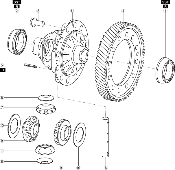
Structural View
bfw2za00000556
|
|
1
|
Taper roller bearing (transaxle case side)
|
|
2
|
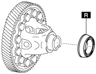
Taper roller bearing (converter housing side)
|
|
3
|
12 bolts
|
|
4
|
Ring gear
|
|
5
|
Roll pin
|
|
6
|
Pinion shaft
|
|
7
|
Pinion gear
|
|
8
|
Thrust washer
|
|
9
|
Side gear
|
|
10
|
Thrust washer
|
|
11
|
Differential gear case
|
Disassembly Procedure
1. Perform the following inspection:
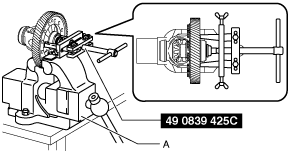
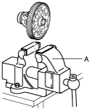
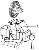
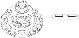
2. Remove the taper roller bearing (transaxle case side) using the following procedure:
bfw2za00000557
|
azzjjw00000952
|
bfw2za00000558
|
azzjjw00001255
|
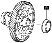
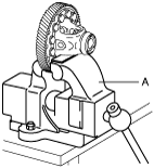
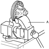
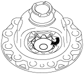
3. Remove the taper roller bearing (converter housing side) using the following procedure:
azzjjw00001256
|
bfw2za00000559
|
bfw2za00000560
|
azzjjw00000958
|
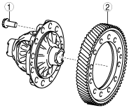
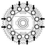
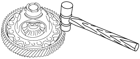
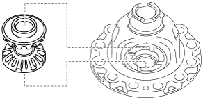
4. Remove the ring gear using the following procedure:
azzjjw00000959
|
|
1
|
12 bolts
|
|
2
|
Ring gear
|
azzjjw00000960
|
azzjjw00000961
|
azzjjw00000958
|
azzjjw00000961
|
bfw2za00000561
|
azzjjw00000963
|
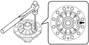
5. Remove the roll pin shown in the figure using a pin punch.
azzjjw00001487
|
bfw2za00001208
|
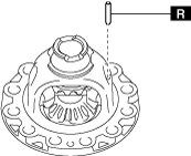
6. Remove the pinion shaft.
azzjjw00001489
|
7. Remove the pinion gears using the following procedure:
azzjjw00001490
|
azzjjw00001491
|
8. Remove the thrust washers from the pinion gears.
azzjjw00001492
|
9. Remove the side gears.
azzjjw00001493
|
10. Remove the thrust washers from the side gears.
azzjjw00001494
|
11. Clean the disassembled parts. (See AUTOMATIC TRANSAXLE CLEANING.)