|
bfw2za00001192
END COVER COMPONENT DISASSEMBLY [EW6A-EL/EW6AX-EL]
id0517006612l4
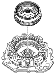
Structural View
bfw2za00001192
|
|
1
|
8 bolts
|
|
2
|
Brake housing
|
|
3
|
2-6 brake piston
|
|
4
|
Springs and retainer component
|
|
5
|
Retaining plate
|
|
6
|
Reduction planetary gear
|
|
7
|
Drive plate
|
|
8
|
Driven plate
|
|
9
|
Retaining plate
|
|
10
|
Thrust needle bearing
|
|
11
|
Reduction internal gear
|
|
12
|
Thrust needle bearing
|
|
13
|
Snap ring
|
|
14
|
Retaining plate
|
|
15
|
Drive plate
|
|
16
|
Driven plate
|
|
17
|
Springs and retainer component
|
|
18
|
R-3-5 brake piston
|
|
19
|
End cover
|
Disassembly Procedure
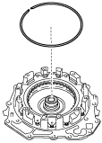
1. Perform a simple inspection of the 2-6 brake using the following procedure:
bfw2za00000563
|
2. Perform a simple inspection of the R-3-5 brake using the following procedure:
bfw2za00000564
|
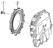
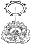
3. Remove the brake housing using the following procedure:
azzjjw00000966
|
|
1
|
8 bolts
|
|
2
|
Brake housing
|
azzjjw00000967
|
azzjjw00000968
|
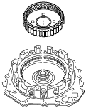
4. Remove the 2-6 brake piston from the brake housing using the following procedure:
azzjjw00000969
|
azzjjw00000970
|
5. Remove the springs and retainer component.
azzjjw00000971
|
6. Remove the retaining plate.
azzjjw00001200
|
7. Remove the reduction planetary gear.
azzjjw00000973
|
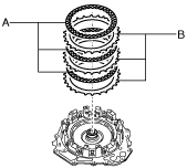
8. Remove the drive plates and driven plates.
azzjjw00000974
|
9. Remove the retaining plate.
azzjjw00000975
|
10. Remove the thrust needle bearing.
azzjjw00000976
|
11. Remove the reduction internal gear.
azzjjw00000977
|
12. Remove the thrust needle bearing.
azzjjw00000978
|
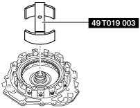
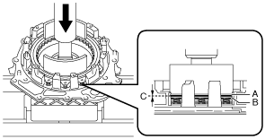
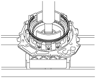
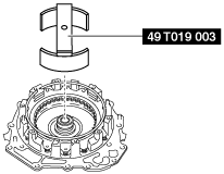
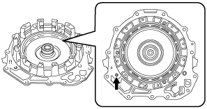
13. Remove the snap ring using the following procedure:
bfw2za00000565
|
bfw2za00000566
|
bfw2za00000567
|
bfw2za00000568
|
bfw2za00000569
|
bfw2za00000570
|
bfw2za00000571
|
azzjjw00000986
|
14. Remove the retaining plate.
azzjjw00000987
|
15. Remove the drive plates and driven plates.
azzjjw00000988
|
16. Remove the springs and retainer component.
azzjjw00000989
|
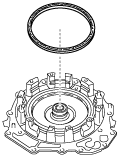
17. Remove the R-3-5 brake piston using the following procedure:
bfw2za00000572
|
azzjjw00000991
|
18. Clean the disassembled parts. (See AUTOMATIC TRANSAXLE CLEANING.)
19. Perform the following inspection and replace a malfunctioning part with a new one.