 |
am3zzw00012216
EXHAUST SYSTEM REMOVAL/INSTALLATION [MZR 2.3 DISI Turbo]
id0115d5800200
1. Remove the battery cover. (See BATTERY REMOVAL/INSTALLATION [MZR 2.3 DISI Turbo].)
2. Disconnect the negative battery cable. (See BATTERY REMOVAL/INSTALLATION [MZR 2.3 DISI Turbo].)
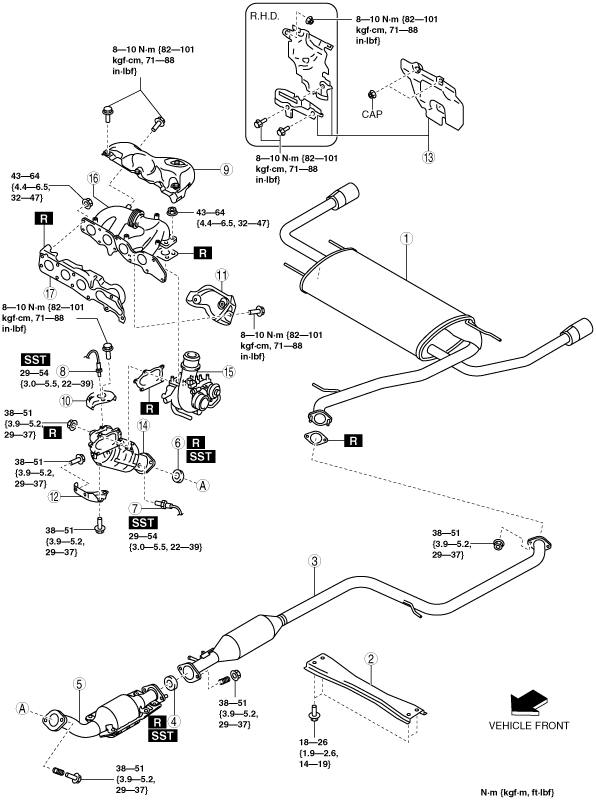
3. Remove in the order indicated in the table.
4. Remove the exhaust system insulator. (See Exhaust System Insulator Removal/installation Note.)
5. Install in the reverse order of removal.
am3zzw00012216
|
|
1
|
Main silencer
|
|
2
|
Tunnel member
|
|
3
|
Middle pipe
|
|
4
|
Seal ring (TWC side)
(See Seal Ring Removal Note.)
|
|
5
|
TWC
(See TWC Installation Note.)
|
|
6
|
Seal ring (WU-TWC side)
(See Seal Ring Removal Note.)
|
|
7
|
HO2S
|
|
8
|
A/F sensor
|
|
9
|
Exhaust manifold upper insulator
|
|
10
|
WU-TWC insulator
|
|
11
|
Exhaust manifold lower insulator
|
|
12
|
WU-TWC bracket
|
|
13
|
Insulator
|
|
14
|
WU-TWC
(See WU-TWC Installation Note.)
|
|
15
|
Turbocharger
|
|
16
|
Exhaust manifold
|
|
17
|
Exhaust manifold gasket
|
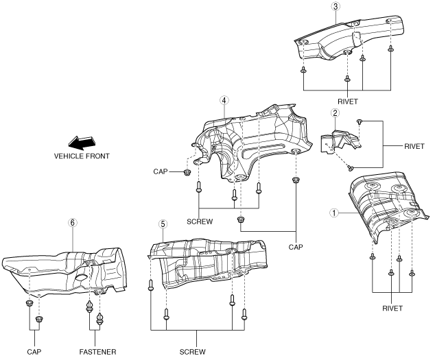
Exhaust System Insulator Removal/installation Note
1. Remove the exhaust system insulator in the order shown in the figure.
2. Install in the reverse order of removal.
am3zzw00012217
|
|
1
|
Insulator (rear No.1)
|
|
2
|
Insulator (rear No.2)
|
|
3
|
Insulator (rear No.3)
|
|
4
|
Insulator (middle No.1)
|
|
5
|
Insulator (middle No.2)
|
|
6
|
Insulator (front)
|
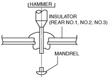
Insulator (Rear No.1, No.2, No.3) Removal Note
1. Push out the mandrel using a hammer and punch (2—2.8 mm {0.08—0.11 in} diameter).
am3uuw00002778
|
2. Remove the flange using a drill (5 mm {0.20 in} drill bit).
ar8uuw00001479
|
Insulator (Front) Removal Note
1. Remove the tunnel member (front).
2. Remove the insulator (front).
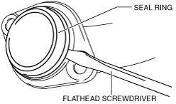
Seal Ring Removal Note
1. Remove the seal ring using a flathead screwdriver being careful not to damage the pipe.
am3uuw00005797
|
Exhaust Manifold Upper Insulator Removal Note
1. Remove the charge air cooler cover. (See INTAKE-AIR SYSTEM REMOVAL/INSTALLATION [MZR 2.3 DISI Turbo].)
2. Remove the charge air cooler. (See INTAKE-AIR SYSTEM REMOVAL/INSTALLATION [MZR 2.3 DISI Turbo].)
3. Remove the charge air cooler bracket. (See INTAKE-AIR SYSTEM REMOVAL/INSTALLATION [MZR 2.3 DISI Turbo].)
4. Remove the exhaust manifold upper insulator.
WU-TWC Insulator Removal Note
1. Remove the turbocharger insulator. (See INTAKE-AIR SYSTEM REMOVAL/INSTALLATION [MZR 2.3 DISI Turbo].)
2. Remove the WU-TWC insulator.
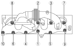
Exhaust Manifold Installation Note
1. Tighten the exhaust manifold installation nuts in the order shown.
am3uuw00005798
|
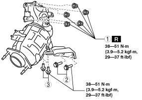
WU-TWC Installation Note
1. Temporarily tighten No.1 shown in the figure.
am3uuw00005799
|
2. Temporarily tighten No.2 shown in the figure.
3. Temporarily tighten No.3 shown in the figure.
4. Completely tighten No.1 shown in the figure.
5. Completely tighten No.2 shown in the figure.
6. Completely tighten No.3 shown in the figure.
Seal Ring (WU-TWC Side) Installation Note
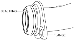
1. Temporarily install the seal ring to the pipe so that the seal ring is even with the flange.
am3uuw00005800
|
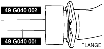
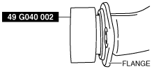
2. Install the SST to the seal ring so that the SST is even with the flange.
am3uuw00005801
|
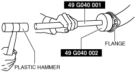
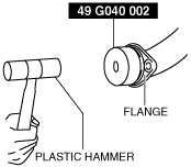
3. Press in the seal ring by tapping the SST using a plastic hammer until the seal ring contacts the flange.
am3uuw00005802
|
TWC Installation Note
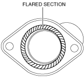
1. Spray carbon remover (TB6601 or equivalent) on the flared section of the exhaust pipe.
am3uuw00005803
|
2. Remove the carbon adhering to the flared section shown in the figure using a nylon brush or sandpaper (No. 400 or equivalent).
Seal Ring (TWC Side) Installation Note
1. Temporarily install the seal ring to the pipe so that the seal ring is even with the flange.
am3uuw00005800
|
2. Install the SST to the seal ring so that the SST is even with the flange.
am3uuw00005804
|
3. Press in the seal ring by tapping the SST using a plastic hammer until the seal ring contacts the flange.
am3uuw00005805
|
Middle Pipe Installation Note
1. Spray carbon remover (TB6601 or equivalent) on the flared section of the exhaust pipe.
am3uuw00005803
|
2. Remove the carbon adhering to the flared section shown in the figure using a nylon brush or sandpaper (No. 400 or equivalent).