DYNAMIC STABILITY CONTROL (DSC)


id041500104600


Outline

•  Hill launch assist (HLA) and vehicle roll prevention function have been adopted, improving safety. (SKYACTIV-G 2.0)

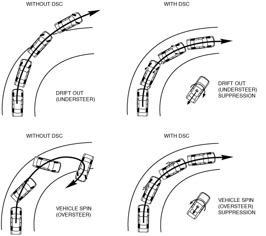
DSC operation outline

•  The ABS prevents wheel lock-up during braking. The TCS detects drive wheel spin due to the accelerator pedal being pressed too hard or similar causes and controls engine speed to suppress wheel spin. With these systems, safety is assured when driving or stopping.
•  Additionally, sudden changes in vehicle attitude, due to evasive steering or road conditions, are controlled by the DSC. The DSC suppresses vehicle sideslip when driving due to vehicle spin (oversteer) or drift-out (understeer) by controlling braking and engine speed. At this time, the TCS/DSC indicator light illuminates to alert the driver that the DSC is operating due to a dangerous situation. As a result, the driver can calmly react and is provided leeway for the next maneuver, resulting in safe driving conditions.
•  In this way the combination of DSC + ABS + TCS ensures driving, stopping and turning safety in all aspects.

Results of DSC operation

am2zzn00000528
Caution
•  While the DSC is a steering safety system, it does not improve normal steering function. Therefore, always drive carefully, even if the vehicle has DSC, and do not overestimate the DSC capability.
•  If the initialization procedures for the brake fluid pressure and low-G sensors are not performed correctly, an incorrectly determined initial point may cause a discrepancy between the actual driving conditions of the vehicle and the signals from the sensors, resulting in improper DSC operation. Therefore, after replacing or removing the following parts, make sure to perform the DSC HU/CM initialization procedures of the sensors with the vehicle stopped on a level ground to insure proper DSC operation. For the initialization procedures of the sensors, refer to the Workshop Manual.
―  DSC HU/CM
•  The DSC and ABS will not operate normally under the following conditions:
―  With tires that are not of the specified size, manufacturer or tread pattern, or not inflated according to specification
―  With tires that have significant comparative wear variation
―  With tire chains
―  With an emergency spare tire


Function

•  The DSC system consists of the following parts. While each part has a regular function in other systems, only the function during DSC control is listed.

Part name

Function

DSC HU/CM
•  Makes calculations using input signals from each sensor, controls brake fluid pressure to each wheel, and actuates each function (ABS, EBD, TCS, DSC, brake assist control, hill launch assist (HLA)*, and vehicle roll prevention function*) of the DSC system.
•  Outputs the torque reduction request signal, wheel speed signal, and DSC system warning control data via CAN lines.
•  Controls the on-board diagnostic system and fail-safe function when there is a malfunction in the DSC system.
PCM
•  Controls engine output based on signals from the DSC HU/CM.
•  Transmits engine speed, tire, and shift position data via CAN communication to the DSC HU/CM.
•  Transmits gear/selector lever position data via CAN communication to the DSC HU/CM.
•  Transmits brake pedal position data via CAN communication to the DSC HU/CM.
TCM (ATX)
•  Transmits gear/selector lever position data via CAN communication to the DSC HU/CM.
BCM
•  Transmits steering angle data via CAN communication to the DSC HU/CM.
DSC indicator light
•  Informs the driver that the DSC is operating (vehicle sideslip occurring).
•  Informs the driver that the TCS is operating (drive wheel is spinning).
•  Informs the driver of DSC/TCS malfunction.
DSC OFF switch
•  Transmits driver intention to release DSC control to the DSC HU/CM.
DSC OFF indicator light
•  Informs driver that DSC control has been released due to DSC OFF switch operation.
ABS wheel-speed sensor
•  Detects the rotation condition of each wheel and transmits it to the DSC HU/CM.
SAS control module
•  Transmits the lateral-G (vehicle lateral acceleration speed), and the yaw rate (vehicle turning angle speed) via CAN communication to the DSC HU/CM.
Brake fluid pressure sensor (Built into DSC HU/CM)
•  Detects the fluid pressure from the master cylinder.

*  :SKYACTIV-G 2.0

Wiring diagram

am3zzn00003417