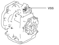
VEHICLE SPEED SENSOR (VSS) INSPECTION [FN4A-EL]
id051701292900
On-Vehicle Inspection
1. Inspect the power supply circuit for the VSS.
- (1) Disconnect the VSS connector.
-
- (2) Switch the ignition to ON (engine off).
- (3) Measure the voltage at VSS connector terminal A (harness-side).
-
-
• If there is any malfunction, repair wiring harness between main relay and VSS.
- (4) Switch the ignition to off.
- (5) Connect the VSS connector.
2. Inspect the GND circuit for the VSS.
- (1) Switch the ignition to off.
- (2) Measure the voltage at VSS sensor connector terminal C (harness-side).
-
-
• If there is any malfunction, repair wiring harness between VSS sensor and GND.
-
VSS specification
-
Below 1.0 V
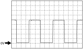
3. Inspect the signal circuit for the VSS.
- (1) Connect the oscilloscope to the following PCM connector terminals and set it as below.
-
-
• (+) lead: PCM terminal 1AX
• (-) lead: battery negative terminal
• Oscilloscope setting: 1 V/DIV (Y), 2 ms/DIV (X), DC range
- (2) Start the engine.
- (3) Measure the wave form when vehicle speed at 30 km/h {19 mph}.
-
-