CVT (CONTINUOUSLY VARIABLE TRANSAXLE) FLUID LEVEL ADJUSTMENT [DJVA-EL]
id051901291200
-
Note
-
• Adjust the CVT fluid level when the TCM is switched to the CVT fluid level adjustment mode and the CVT fluid is at the appropriate temperature (between 35 °C {95 °F} and under 45 °C {113 °F}).
• Perform the following procedure for the CVT fluid level adjustment.
-
CVT Fluid Replenishment
• Refer to the following items before adding CVT fluid because the CVT fluid replenishment procedure differs depending on the performed service.
-
CVT fluid in oil pan draining
1. Remove the filler plug and the gasket.
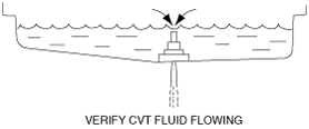
2. Add the CVT fluid from the filler plug orifice until the CVT fluid starts flowing from the overflow orifice.
-
Specified CVT fluid
-
Mobil CVTF 3320
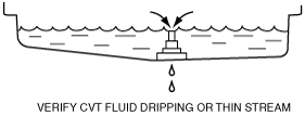
3. Allow the CVT to drain from the overflow orifice until it drips or becomes a thin stream.
4. Temporarily tighten the overflow plug reusing the gasket.
5. Add the CVT fluid from the filler plug orifice.
-
CVT fluid replenishment amount
-
0.5 L {0.5 US qt, 0.4 lmp qt}
6. Temporarily tighten the filler plug reusing the gasket.
7. Go to “CVT Fluid Level Adjustment Mode Switching”. (See CVT Fluid Level Adjustment Mode Switching.)
CVT newly replaced
1. Remove the filler plug and the gasket.
2. Add the CVT fluid from the filler plug orifice.
-
Specified CVT fluid
-
Mobil CVTF 3320
-
CVT fluid replenishment amount
-
3.4 L {3.6 US qt, 3.0 lmp qt}
3. Temporarily tighten the filler plug reusing the gasket.
4. Go to “CVT Fluid Level Adjustment Mode Switching”. (See CVT Fluid Level Adjustment Mode Switching.)
CVT Fluid Level Adjustment Mode Switching
-
Note
-
• Perform the procedure for switching to the CVT fluid level adjustment mode within 3 min. If the procedure is not completed within 3 min, the switching procedure is cancelled.
• If the flashing of each light cannot be verified as according to the procedure while switching to the CVT fluid level adjustment mode, the switching procedure has failed. Repeat the procedure from the beginning.
1. Apply the parking brake firmly.
2. Turn the A/C switch off.
3. Perform the following and verify that the gear position indicator light flashes 2 times.
- (1) Switch the ignition to ACC.
- (2) Depress the brake pedal with the left foot and hold it in that condition (continue to depress the brake pedal until Step 5 is completed).
- (3) Select the selector lever from the P position to the M range.
- (4) Depress the accelerator pedal with the right foot all the way down and hold it in that condition (continue to depress the brake pedal until Step 4 (3) is completed).
- (5) Select the selector lever to the M (+) or M (-) and hold it in that condition.
- (6) Switch the ignition ON (engine off).
- (7) Verify that the gear position indicator light flashes 2 times after approx. 5 s.
4. Perform the following procedure and verify that the N position display of the selector indicator light flashes 2 times.
-
Note
-
• Slowly and firmly select the selector lever operation.
- (1) Select the selector lever in the order of M range→D range→N position→R position→P position.
- (2) Select the selector lever in the order of P position→R position→N position.
- (3) Remove the right foot from the accelerator pedal.
- (4) Verify that the N position display flashes 2 times.
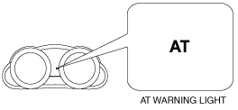
5. Perform the following procedure and verify that the AT warning light flashes 2 times.
- (1) Start the engine.
- (2) Select the selector lever quickly between the N position and the D range for 6 s or more.
- (3) Verify that the AT warning light flashes 2 times.
6. Perform the following procedure and verify that the P position display flashes.
-
Note
-
• Select the selector lever to each position/range and hold for 2 s or more.
- (1) Select the selector lever to the P position.
- (2) Select the selector lever in the order of P position→R position→N position→D range.
- (3) Select the selector lever in the order of D range→N position→R position→P position.
- (4) Select the selector lever in the order of P position→R position→N position→D range.
- (5) Select the selector lever in the order of D range→N position→R position→P position.
- (6) Verify that the TCM switches to the CVT fluid level adjustment mode via the P position display flashing.
7. Go to “CVT Fluid Level Adjustment”. (See CVT Fluid Level Adjustment.)
CVT Fluid Level Adjustment
-
Note
-
• Adjust the CVT fluid level when the TCM is switched to the CVT fluid level adjustment mode and the CVT fluid is at the appropriate temperature (between 35 °C {95 °F} and under 45 °C {113 °F}).
• Be careful not to perform the following when performing “CVT Fluid Level Adjustment”.
-
― Do not stop the engine.
― Do not depress the accelerator pedal.
― Do not drive the vehicle.
1. Verify the CVT fluid temperature.
-
• Using the M-MDS
-
― Verify the CVT fluid temperature using the PID/data monitor function“TFT”. (See ON-BOARD DIAGNOSTIC SYSTEM DTC INSPECTION [DJVA-EL].)
• Using the selector indicator light
-
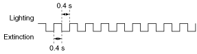
― Verify the CVT fluid temperature using the P position display flashing pattern.
|
CVT fluid temperature
|
Selector indicator light (P position display) flashing pattern
|
|
High temperature
(45 °C {113 °F} or more)
|
 |
|
Appropriate temperature
(between 35 °C {95 °F} and under 45 °C {113 °F})
|
 |
|
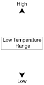
Low temperature
(less than 35 °C {95 °F})
|
 |
 |
 |
 |
2. Warm up the engine while idling it until the CVT fluid temperature reaches the lower limit of 35 °C {95 °F}.
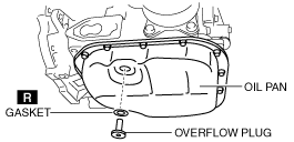
3. Remove the overflow plug and the gasket while leaving the engine idling.
4. Verify that CVT fluid flows from the overflow orifice.
-
Note
-
• For a low amount of CVT fluid flowing from the overflow orifice, the fluid level is not adjusted to the specification because the fluid that has accumulated in the overflow tube is what has flowed from the orifice.
5. Allow the CVT to drain from the overflow orifice until it drips or becomes a thin stream.
6. Install a new gasket and overflow plug.
-
Tightening torque
-
40 N·m {4.1 kgf·m, 30 ft·lbf}
7. Stop the engine.
8. Install a new gasket and filler plug.
-
Tightening torque
-
40—58 N·m {4.1—5.9 kgf·m, 30—42 ft·lbf}
9. Install the aerodynamic undercover No.2. (See AERODYNAMIC UNDERCOVER NO.2 REMOVAL/INSTALLATION.)