 |
am3zzw00011325
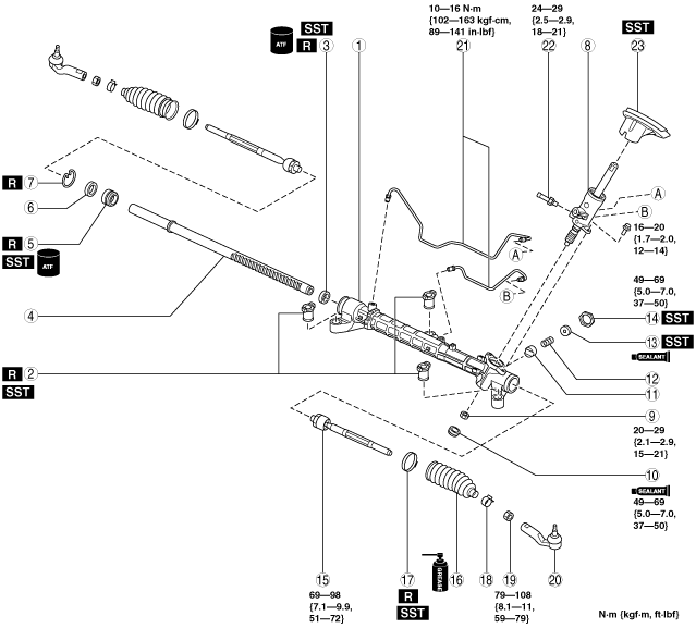
STEERING GEAR AND LINKAGE ASSEMBLY
id061400801200
1. Assemble in the order indicated in the table.
L.H.D.
am3zzw00011325
|
|
1
|
Gear housing
|
|
2
|
Mounting rubber
|
|
3
|
Oil seal
(See Oil Seal Assembly Note.)
|
|
4
|
Steering rack
(See Steering Rack Assembly Note.)
|
|
5
|
Rack bushing
|
|
6
|
Stopper
|
|
7
|
Clip
|
|
8
|
Pinion shaft and valve housing component
|
|
9
|
Locknut (on pinion shaft)
|
|
10
|
Housing cover
(See Housing Cover Assembly Note.)
|
|
11
|
Support yoke
|
|
12
|
Yoke spring
|
|
13
|
Adjusting cover
|
|
14
|
Locknut (on adjusting cover)
|
|
15
|
Tie rod
|
|
16
|
Boot
(See Boot Assembly Note.)
|
|
17
|
Boot band
(See Boot Band Assembly Note.)
|
|
18
|
Boot clamp
|
|
19
|
Locknut
|
|
20
|
Tie-rod end
(See Tie-rod End Assembly Note.)
|
|
21
|
Oil pipe
|
|
22
|
Return pipe
|
|
23
|
Floor seal
(See Floor Seal Assembly Note.)
|
R.H.D.
am3zzw00011326
|
|
1
|
Gear housing
|
|
2
|
Mounting rubber
|
|
3
|
Oil seal
(See Oil Seal Assembly Note.)
|
|
4
|
Steering rack
(See Steering Rack Assembly Note.)
|
|
5
|
Rack bushing
|
|
6
|
Stopper
|
|
7
|
Clip
|
|
8
|
Pinion shaft and valve housing component
|
|
9
|
Locknut (on pinion shaft)
|
|
10
|
Housing cover
(See Housing Cover Assembly Note.)
|
|
11
|
Support yoke
|
|
12
|
Yoke spring
|
|
13
|
Adjusting cover
|
|
14
|
Locknut (on adjusting cover)
|
|
15
|
Tie rod
|
|
16
|
Boot
(See Boot Assembly Note.)
|
|
17
|
Boot band
(See Boot Band Assembly Note.)
|
|
18
|
Boot clamp
|
|
19
|
Locknut
|
|
20
|
Tie-rod end
(See Tie-rod End Assembly Note.)
|
|
21
|
Oil pipe
|
|
22
|
Return pipe
|
|
23
|
Floor seal
(See Floor Seal Assembly Note.)
|
Mounting Rubber Assembly Note
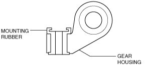
1. Apply soapy water to the rubber part of the mounting rubber.
2. Install the mounting rubber so that two projections of the mounting rubber are parallel to the steering rack as shown in the figure.
am3uuw00003179
|
3. Press fit the ear portion of the mounting rubber (lower side) using the SSTs until it projects from the gear housing as shown in the figure.
am3uuw00003180
|
4. Reverse the gear housing, then Press fit the mounting rubber using the SSTs and the press until the mounting rubber ear portion (upper side) contacts the gear housing.
am3uuw00004666
|
5. Verify that both mounting rubber ears are correctly assembled with no gaps between them and the gear housing as shown in the figure.
am3uuw00003182
|
Oil Seal Assembly Note
1. Apply ATF to the lip of a new oil seal.
2. Install the SST (49 N032 319A) to the gear housing as shown in the figure.
am3uuw00003230
|
3. Set the gear housing into the press and insert the oil seal in the gear housing so that groove area is facing up as shown in the figure.
am3uuw00004707
|
4. Set the stopper into the gear housing to hold the SSTs as shown in the figure.
am3uuw00003183
|
5. Install the oil seal using the SSTs (49 F032 303, 49 F032 304) and a press.
Steering Rack Assembly Note
1. Apply multipurpose grease to the rack teeth.
2. Install a plastic bag to the rack teeth and insert the steering rack in the gear housing.
am3uuw00003204
|
Rack Bushing, Stopper and Clip Assembly Note
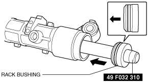
1. Apply ATF to the rack bushing.
2. After installing the SST to the steering rack end, assemble the rack bushing to the rack housing.
am3uuw00003185
|
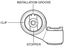
3. Insert the stopper together with the rack bushing to the rack housing so that the stopper extends past the installation groove on the rack housing.
4. Assemble the clip to the installation groove on the rack housing.
am3uuw00003186
|
5. Perform the cylinder air tightness inspection using the following procedure.
am3uuw00003187
|
6. Install the SST to the power cylinder section of the gear housing.
7. Apply 53.3 kPa {400 mmHg, 15.7 inHg} of vacuum with a vacuum pump and verify that it holds for 30 s.
Pinion Shaft and Valve Housing Component Assembly Note
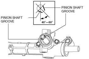
1. Set the rack in the center with the measurement between rack housing end and rack end as shown in the figure.
am3uuw00004708
|
2. When the pinion shaft position is as shown in the figure with the rack in the center, insert the pinion shaft and valve housing component.
L.H.D.
am3zzw00005421
|
R.H.D.
am3zzw00008492
|
Housing Cover Assembly Note
1. Apply silicone sealant to the threads of the housing cover.
2. Assemble the housing cover.
Adjusting Cover, Locknut (on Adjusting Cover) Assembly Note
1. Apply sealant to the threads of the adjusting cover.
2. Tighten the adjusting cover with a tightening torque of 20—29 N·m {2.1—2.9 kgf·m, 15—21 ft·lbf}.
3. Using the SST, loosen the adjusting cover to 25—30°.
am3uuw00003190
|
4. Fix the adjusting cover and tighten the locknut using the SST.
am3uuw00003191
|
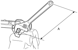
5. Measure the rotation torque of the pinion shaft using a crescent wrench and pull scale.
am3uuw00003192
|
am3uuw00003193
|
6. If not as specified, remove the locknut and adjust the adjust cover.
Boot Assembly Note
1. Apply silicone grease to the rubber lip groove.
2. Assemble the boot.
Boot Band Assembly Note
1. Assemble the boot band to the boot.
2. Crimp the boot band using the SST.
am3zzw00009652
|
3. Rotate the boot by hand and verify that it is securely installed to the boot band.
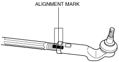
Tie-rod End Assembly Note
1. Align the alignment marks made before removing the tie-rod end, and then assemble it to the tie-rod.
am3uuw00003165
|
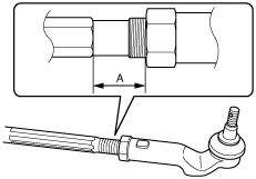
2. Adjust dimension A shown in the figure to the standard, and assemble.
am3uuw00003194
|
Floor Seal Assembly Note
1. Assemble the floor seal using the SST and a press, steel plate.
am3uuw00003195
|