|
am3zzn00003193
FULL AUTO AIR CONDITIONER [FULL-AUTO AIR CONDITIONER]
id0740a1126300
Block Diagram
am3zzn00003193
|
Control Table
|
Basic control |
Control description |
Correction control |
|---|---|---|
|
Airflow temperature control
|
Airflow temperature automatic control
|
• MAX HOT and MAX COLD correction
|
|
Airflow volume control
|
Airflow volume automatic control
|
• Engine coolant temperature correction (warm-up correction)
• Mild start correction
• MAX HOT and MAX COLD correction
• Window fogging prevention correction at start
• Starting compensation correction
• Defroster correction
• Starting burnt-out prevention function
|
|
Airflow volume manual control
|
• Defroster correction
• Starting burnt-out prevention function
|
|
|
Airflow mode control
|
Airflow mode automatic control
|
• Engine coolant temperature correction (warm-up correction)
|
|
Airflow mode manual control
|
―
|
|
|
Air intake control
|
Air intake control
|
• Defroster correction
• Ambient temperature correction
|
|
A/C compressor control
|
A/C compressor automatic control
|
• Defroster correction
|
|
A/C compressor manual control
|
• Defroster correction
|
|
Supplementary function |
|---|
|
Fail-safe function
|
|
Sensor signal delay function
|
|
On-board diagnostic function
|
Control Type Transition by Switch Operation
Airflow temperature control, airflow volume control (European (L.H.D. U.K.) specs.)
|
Operation switch |
Airflow temperature control |
Airflow volume control |
||||||||||
|---|---|---|---|---|---|---|---|---|---|---|---|---|
|
Control prior to switch operation |
Control prior to switch operation |
|||||||||||
|
Automatic control |
Automatic control |
Defroster correction |
Manual control |
|||||||||
|
OFF |
1 |
2 |
3 |
4 |
5 |
6 |
7 |
|||||
|
OFF switch
|
Automatic control
|
OFF
|
OFF
|
OFF
|
||||||||
|
AUTO switch
|
Automatic control
|
Automatic control
|
Automatic control
|
Automatic control
|
||||||||
|
Airflow volume control dial
|
HI
|
Automatic control
|
Manual control*2
|
Manual control*2
|
1
|
2
|
3
|
4
|
5
|
6
|
7
|
7
|
|
LO
|
Automatic control
|
Manual control*3
|
Manual control*3
|
1
|
1
|
1
|
2
|
3
|
4
|
5
|
6
|
|
|
MODE switch
|
Automatic control
|
Automatic control
|
Automatic control*4
|
No change
|
||||||||
|
DEFROSTER switch
|
Automatic control
|
Defroster correction
|
Automatic control*4
|
Defroster correction
|
||||||||
|
A/C switch
|
Automatic control
|
Automatic control
|
No change
|
*5
|
No change
|
|||||||
|
REC switch
|
Automatic control
|
Automatic control
|
No change
|
No change
|
||||||||
|
Driver-side temperature setting dial*1
|
15.0/60
|
MAX COLD
|
MAX HI*6
|
MAX HI*6
|
No change
|
|||||||
|
15.5—28.5/
61—83
|
Automatic control
|
Automatic control
|
No change
|
No change
|
||||||||
|
29.0/84
|
MAX HOT
|
AUTO HI*6
|
AUTO HI*6
|
No change
|
||||||||
|
Passenger-side temperature setting dial
|
15.0/60
|
MAX COLD
|
MAX HI*6
|
MAX HI*6
|
No change
|
|||||||
|
15.5—28.5/
61—83
|
Automatic control
|
Automatic control
|
No change
|
No change
|
||||||||
|
29.0/84
|
MAX HOT
|
AUTO HI*6
|
AUTO HI*6
|
No change
|
||||||||
|
Dual switch
|
Automatic control
|
No change
|
No change
|
No change
|
||||||||
Airflow temperature control, airflow volume control (Australian, General (L.H.D. R.H.D.) specs.)
|
Operation switch |
Airflow temperature control |
Airflow volume control |
||||||||||
|---|---|---|---|---|---|---|---|---|---|---|---|---|
|
Control prior to switch operation |
Control prior to switch operation |
|||||||||||
|
Automatic control |
Automatic control |
Defroster correction |
Manual control |
|||||||||
|
OFF |
1 |
2 |
3 |
4 |
5 |
6 |
7 |
|||||
|
OFF switch
|
Automatic control
|
OFF
|
OFF
|
OFF
|
||||||||
|
AUTO switch
|
Automatic control
|
Automatic control
|
Automatic control
|
Automatic control
|
||||||||
|
Airflow volume control dial
|
HI
|
Automatic control
|
Manual control*2
|
Manual control*2
|
1
|
2
|
3
|
4
|
5
|
6
|
7
|
7
|
|
LO
|
Automatic control
|
Manual control*3
|
Manual control*3
|
1
|
1
|
1
|
2
|
3
|
4
|
5
|
6
|
|
|
MODE switch
|
Automatic control
|
Automatic control
|
Automatic control*4
|
No change
|
||||||||
|
DEFROSTER switch
|
Automatic control
|
Defroster correction
|
Automatic control*4
|
Defroster correction
|
||||||||
|
A/C switch
|
Automatic control
|
Automatic control
|
No change
|
*5
|
No change
|
|||||||
|
REC switch
|
Automatic control
|
Automatic control
|
No change
|
No change
|
||||||||
|
Driver-side temperature setting dial*1
|
18.0/64
|
MAX COLD
|
MAX HI*6
|
MAX HI*6
|
No change
|
|||||||
|
18.5—31.5/
65—89
|
Automatic control
|
Automatic control
|
No change
|
No change
|
||||||||
|
32.0/90
|
MAX HOT
|
AUTO HI*6
|
AUTO HI*6
|
No change
|
||||||||
|
Passenger-side temperature setting dial
|
18.0/64
|
MAX COLD
|
MAX HI*6
|
MAX HI*6
|
No change
|
|||||||
|
18.5—31.5/
65—89
|
Automatic control
|
Automatic control
|
No change
|
No change
|
||||||||
|
32.0/90
|
MAX HOT
|
AUTO HI*6
|
AUTO HI*6
|
No change
|
||||||||
|
Dual switch
|
Automatic control
|
No change
|
No change
|
No change
|
||||||||
Airflow mode control, air intake control, A/C compressor control (European (L.H.D. U.K.) specs.)
|
Operation switch |
Airflow mode control |
Air intake control |
A/C compressor control |
||||
|---|---|---|---|---|---|---|---|
|
Control prior to switch operation |
Control prior to switch operation |
Control prior to switch operation |
|||||
|
Automatic control |
Manual control |
Automatic control |
Manual control |
Automatic control |
Manual control |
||
|
OFF switch
|
Fixed at mode before turned OFF
|
No change
|
Fixed at mode before turned OFF
|
No change
|
OFF
|
OFF
|
|
|
AUTO switch
|
Automatic control
|
Automatic control
|
Automatic control
|
Automatic control
|
Automatic control
|
Automatic control
|
|
|
Airflow volume control dial
|
HI
|
Automatic control
|
No change
|
Automatic control
|
No change
|
Automatic control
|
No change
|
|
LO
|
Automatic control
|
No change
|
Automatic control
|
No change
|
Automatic control
|
No change
|
|
|
MODE switch
|
Up
|
VENT → BI-LEVEL
BI-LEVEL → HEAT
HEAT → DEF/HEAT
DEF/HEAT → VENT
|
VENT → BI-LEVEL
BI-LEVEL → HEAT
HEAT → DEF/HEAT
DEF/HEAT → VENT
|
Automatic control
|
No change
|
Automatic control
|
No change
|
 |
|||||||
|
Down
|
VENT → DEF/HEAT
DEF/HEAT → HEAT
HEAT → BI-LEVEL
BI-LEVEL → VENT
DEFROSTER (warm-up) → HEAT
|
VENT → DEF/HEAT
DEF/HEAT → HEAT
HEAT → BI-LEVEL
BI-LEVEL → VENT
DEFROSTER (manual) → HEAT
|
Automatic control
|
No change
|
Automatic control
|
No change
|
|
 |
|||||||
|
DEFROSTER switch
|
DEFROSTER
|
DEFROSTER
|
Defroster correction
|
Defroster correction
|
Defroster correction
|
Defroster correction
|
|
|
A/C switch
|
Automatic control
|
No change
|
Automatic control
|
No change
|
A/C→OFF
OFF→A/C
|
A/C→OFF
OFF→A/C
|
|
|
REC switch
|
Automatic control
|
No change
|
FRESH→REC
REC→FRESH
|
FRESH→REC
REC→FRESH
|
Automatic control
|
No change
|
|
|
Driver-side temperature setting dial*1
|
15.0/60
|
Automatic control
|
No change
|
Automatic control
|
No change
|
Automatic control
|
No change
|
|
15.5—28.5/
61—83
|
Automatic control
|
No change
|
Automatic control
|
No change
|
Automatic control
|
No change
|
|
|
29.0/84
|
Automatic control
|
No change
|
Automatic control
|
No change
|
Automatic control
|
No change
|
|
|
Passenger-side temperature setting dial
|
15.0/60
|
Automatic control
|
No change
|
Automatic control
|
No change
|
Automatic control
|
No change
|
|
15.5—28.5/
61—83
|
Automatic control
|
No change
|
Automatic control
|
No change
|
Automatic control
|
No change
|
|
|
29.0/84
|
Automatic control
|
No change
|
Automatic control
|
No change
|
Automatic control
|
No change
|
|
|
Dual switch
|
Automatic control
|
No change
|
Automatic control
|
No change
|
No change
|
No change
|
|
Airflow mode control, air intake control, A/C compressor control (Australian, General(L.H.D. R.H.D.) specs.)
|
Operation switch |
Airflow mode control |
Air intake control |
A/C compressor control |
||||
|---|---|---|---|---|---|---|---|
|
Control prior to switch operation |
Control prior to switch operation |
Control prior to switch operation |
|||||
|
Automatic control |
Manual control |
Automatic control |
Manual control |
Automatic control |
Manual control |
||
|
OFF switch
|
Fixed at mode before turned OFF
|
No change
|
Fixed at mode before turned OFF
|
No change
|
OFF
|
OFF
|
|
|
AUTO switch
|
Automatic control
|
Automatic control
|
Automatic control
|
Automatic control
|
Automatic control
|
Automatic control
|
|
|
Airflow volume control dial
|
HI
|
Automatic control
|
No change
|
Automatic control
|
No change
|
Automatic control
|
No change
|
|
LO
|
Automatic control
|
No change
|
Automatic control
|
No change
|
Automatic control
|
No change
|
|
|
MODE switch
|
Up
|
VENT → BI-LEVEL
BI-LEVEL → HEAT
HEAT → DEF/HEAT
DEF/HEAT → VENT
|
VENT → BI-LEVEL
BI-LEVEL → HEAT
HEAT → DEF/HEAT
DEF/HEAT → VENT
|
Automatic control
|
No change
|
Automatic control
|
No change
|
|
|||||||
|
Down
|
VENT → DEF/HEAT
DEF/HEAT → HEAT
HEAT → BI-LEVEL
BI-LEVEL → VENT
DEFROSTER → HEAT
|
VENT → DEF/HEAT
DEF/HEAT → HEAT
HEAT → BI-LEVEL
BI-LEVEL → VENT
DEFROSTER → HEAT
|
Automatic control
|
No change
|
Automatic control
|
No change
|
|
|
|||||||
|
DEFROSTER switch
|
DEFROSTER
|
DEFROSTER
|
Defroster correction
|
Defroster correction
|
Defroster correction
|
Defroster correction
|
|
|
A/C switch
|
Automatic control
|
No change
|
Automatic control
|
No change
|
A/C→OFF
OFF→A/C
|
A/C→OFF
OFF→A/C
|
|
|
REC switch
|
Automatic control
|
No change
|
FRESH→REC
REC→FRESH
|
FRESH→REC
REC→FRESH
|
Automatic control
|
No change
|
|
|
Driver-side temperature setting dial*1
|
18.0/64
|
Automatic control
|
No change
|
Automatic control
|
No change
|
Automatic control
|
No change
|
|
18.5—31.5/
65—89
|
Automatic control
|
No change
|
Automatic control
|
No change
|
Automatic control
|
No change
|
|
|
32.0/90
|
Automatic control
|
No change
|
Automatic control
|
No change
|
Automatic control
|
No change
|
|
|
Passenger-side temperature setting dial
|
18.0/64
|
Automatic control
|
No change
|
Automatic control
|
No change
|
Automatic control
|
No change
|
|
18.5—31.5/
65—89
|
Automatic control
|
No change
|
Automatic control
|
No change
|
Automatic control
|
No change
|
|
|
32.0/90
|
Automatic control
|
No change
|
Automatic control
|
No change
|
Automatic control
|
No change
|
|
|
Dual switch
|
Automatic control
|
No change
|
Automatic control
|
No change
|
No change
|
No change
|
|
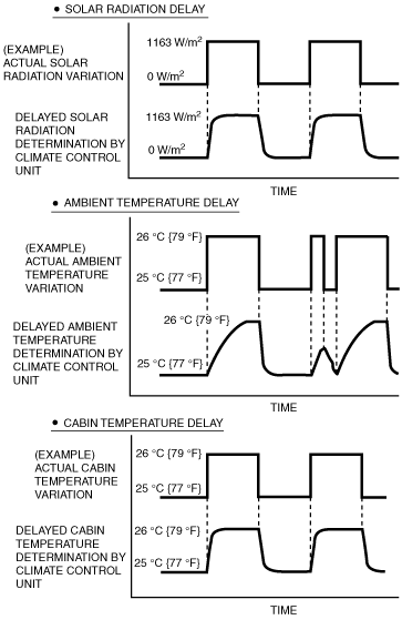
Sensor Signal Delay Function
am3zzn00003194
|