|
am3zzw00010502
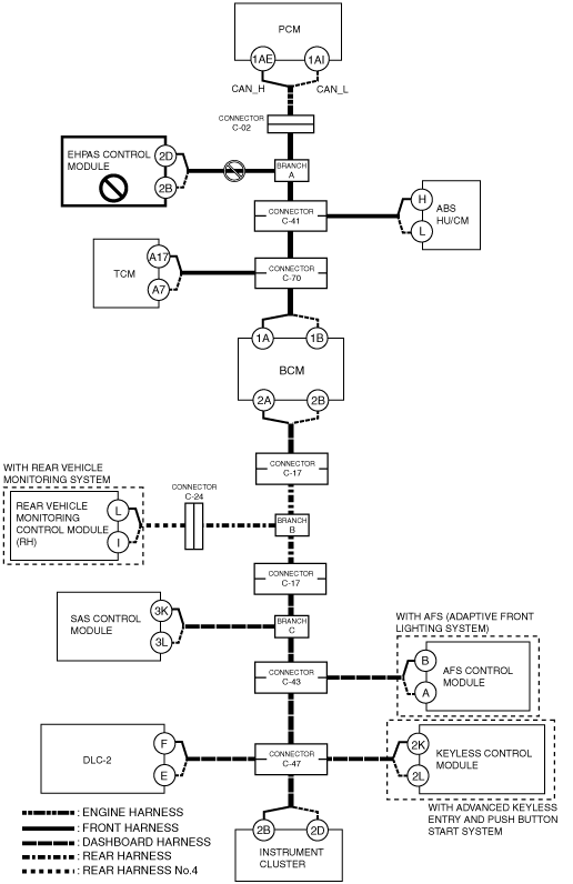
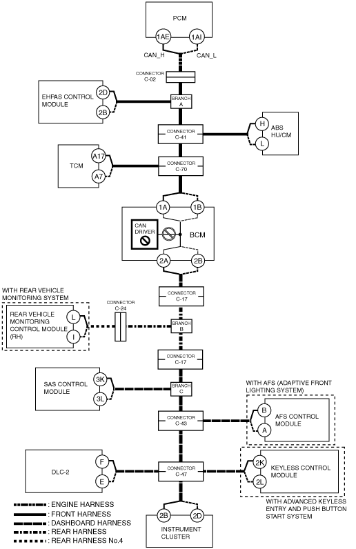
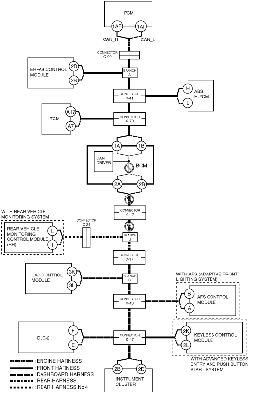
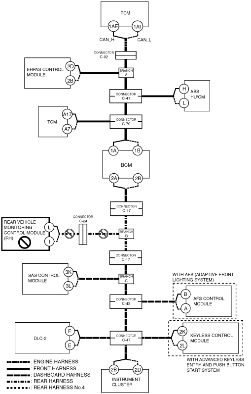
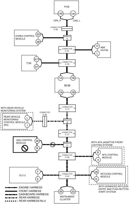
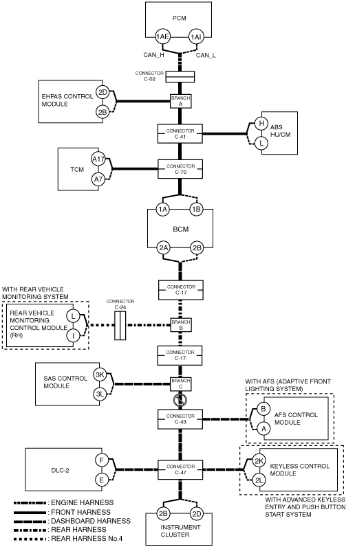
DETERMINING OPEN CIRCUIT LOCATION (HS-CAN) [MULTIPLEX COMMUNICATION SYSTEM (R.H.D. (MZR 1.5))]
id0902m9837900
1. Verify the CAN system-related module DTCs and the failed module on the M-MDS screen.
2. Apply the communication error DTC and the failed module to DTC output pattern and malfunctioning part, and select the possible cause for the diagnostic result and the reference for the inspection item.
3. Inspect the possible cause and inspection item of the applicable malfunctioning part.
4. After repairing, return to CONTROLLER AREA NETWORK (CAN) MALFUNCTION DIAGNOSIS FLOW [MULTIPLEX COMMUNICATION SYSTEM (R.H.D. (MZR 1.5))] and verify that the repairs have been completed.
DTC output pattern and malfunctioning part
|
M-MDS display |
DTC output pattern and malfunctioning part |
|||||||||||||||||
|---|---|---|---|---|---|---|---|---|---|---|---|---|---|---|---|---|---|---|
|
DTC output module |
DTC |
|||||||||||||||||
|
PCM
(PCM)
|
U0101:00
|
|
|
|
|
|
×
|
|
|
|
|
|
|
|
|
|
|
|
|
U0121:00
|
|
|
|
×
|
|
|
|
|
|
|
|
|
|
|
|
|
|
|
|
U0131:00
|
|
×
|
|
|
|
|
|
|
|
|
|
|
|
|
|
|
|
|
|
U0155:00
|
|
|
|
|
|
|
|
|
|
|
|
|
|
|
|
|
×
|
|
|
EPS
(EHPAS control module)
|
U0100
|
×
|
|
|
|
|
|
|
|
|
|
|
|
|
|
|
|
|
|
U0140
|
|
|
|
|
|
|
|
×
|
|
|
|
|
|
|
|
|
|
|
|
U0155
|
|
|
|
|
|
|
|
|
|
|
|
|
|
|
|
|
×
|
|
|
ABS
(ABS HU/CM)
|
U0100:00
|
×
|
|
×
|
|
|
|
|
|
|
|
|
|
|
|
|
|
|
|
U0155:00
|
|
|
|
|
|
|
|
|
|
|
|
|
|
|
|
|
×
|
|
|
TCM
(TCM)
|
U0100:00
|
×
|
|
×
|
|
×
|
|
|
|
|
|
|
|
|
|
|
|
|
|
U0121:00
|
|
|
|
×
|
×
|
|
|
|
|
|
|
|
|
|
|
|
|
|
|
BCM/GEM
(BCM)
|
U0100:00
|
×
|
|
×
|
|
×
|
|
×
|
|
|
|
|
|
|
|
|
|
|
|
U0101:00
|
|
|
|
|
|
×
|
×
|
|
|
|
|
|
|
|
|
|
|
|
|
U0121:00
|
|
|
|
×
|
×
|
|
×
|
|
|
|
|
|
|
|
|
|
|
|
|
U0151:00
|
|
|
|
|
|
|
|
|
|
|
|
×
|
|
|
|
|
|
|
|
U0214:00
|
|
|
|
|
|
|
|
|
|
|
|
|
|
|
|
×
|
|
|
|
RVM*1
(Rear vehicle monitoring control module (RH))
|
U0100:00
|
×
|
|
×
|
|
×
|
|
×
|
|
×
|
|
|
|
|
|
|
|
|
|
U0101:00
|
|
|
|
|
|
×
|
×
|
|
×
|
|
|
|
|
|
|
|
|
|
|
U0121:00
|
|
|
|
×
|
×
|
|
×
|
|
×
|
|
|
|
|
|
|
|
|
|
|
U0140:00
|
|
|
|
|
|
|
|
×
|
×
|
|
|
|
|
|
|
|
|
|
|
U0155:00
|
|
|
|
|
|
|
|
|
|
|
|
|
|
|
|
|
×
|
|
|
RCM
(SAS control module)
|
U0155
|
|
|
|
|
|
|
|
|
|
|
|
|
|
|
|
|
×
|
|
AFS*2
(AFS control module)
|
U0100:00
|
×
|
|
×
|
|
×
|
|
×
|
|
×
|
|
×
|
|
×
|
|
|
|
|
|
U0140:00
|
|
|
|
|
|
|
|
×
|
×
|
|
×
|
|
×
|
|
|
|
|
|
|
RKE*3
(Keyless control module)
|
U0100:00
|
×
|
|
×
|
|
×
|
|
×
|
|
×
|
|
×
|
|
×
|
|
×
|
|
|
|
U0101:00
|
|
|
|
|
|
×
|
×
|
|
×
|
|
×
|
|
×
|
|
×
|
|
|
|
|
U0121:00
|
|
|
|
×
|
×
|
|
×
|
|
×
|
|
×
|
|
×
|
|
×
|
|
|
|
|
IC
(Instrument cluster)
|
U0100:00
|
×
|
|
×
|
|
×
|
|
×
|
|
×
|
|
×
|
|
×
|
|
×
|
|
|
|
U0101:00
|
|
|
|
|
|
×
|
×
|
|
×
|
|
×
|
|
×
|
|
×
|
|
|
|
|
U0121:00
|
|
|
|
×
|
×
|
|
×
|
|
×
|
|
×
|
|
×
|
|
×
|
|
|
|
|
U0131:00
|
|
×
|
×
|
|
×
|
|
×
|
|
×
|
|
×
|
|
×
|
|
×
|
|
|
|
|
U0140:00
|
|
|
|
|
|
|
|
×
|
×
|
|
×
|
|
×
|
|
×
|
|
|
|
|
U0151:00
|
|
|
|
|
|
|
|
|
|
|
|
×
|
×
|
|
×
|
|
|
|
|
U0182:00
|
|
|
|
|
|
|
|
|
|
|
|
|
|
×
|
×
|
|
|
|
|
U0214:00
|
|
|
|
|
|
|
|
|
|
|
|
|
|
|
|
×
|
|
|
|
U0232:00
|
|
|
|
|
|
|
|
|
|
×
|
×
|
|
×
|
|
×
|
|
|
|
|
M-MDS display module
|
[Fail] display pattern
|
|||||||||||||||||
|
PCM
|
×
|
|
×
|
|
×
|
|
×
|
|
×
|
|
×
|
|
×
|
|
×
|
|
|
|
|
EPS
|
|
×
|
×
|
|
×
|
|
×
|
|
×
|
|
×
|
|
×
|
|
×
|
|
|
|
|
ABS
|
|
|
|
×
|
×
|
|
×
|
|
×
|
|
×
|
|
×
|
|
×
|
|
|
|
|
TCM
|
|
|
|
|
|
×
|
×
|
|
×
|
|
×
|
|
×
|
|
×
|
|
|
|
|
BCM/GEM
|
|
|
|
|
|
|
|
×
|
×
|
|
×
|
|
×
|
|
×
|
|
|
|
|
RVM*1
|
|
|
|
|
|
|
|
|
|
×
|
×
|
|
×
|
|
×
|
|
|
|
|
RCM
|
|
|
|
|
|
|
|
|
|
|
|
×
|
×
|
|
×
|
|
|
|
|
AFS*2
|
|
|
|
|
|
|
|
|
|
|
|
|
|
×
|
×
|
|
|
|
|
RKE*3
|
|
|
|
|
|
|
|
|
|
|
|
|
|
|
|
×
|
|
|
|
IC
|
|
|
|
|
|
|
|
|
|
|
|
|
|
|
|
|
×
|
|
|
Diagnostic result
|
||||||||||||||||||
|
Possible cause and inspection item
|
A
|
B
|
C
|
D
|
E
|
F
|
G
|
H
|
I
|
J
|
K
|
L
|
M
|
N
|
O
|
P
|
Q
|
|
|
Reference page
|
||||||||||||||||||
A
Possible cause
System wiring diagram
am3zzw00010502
|
Inspection item
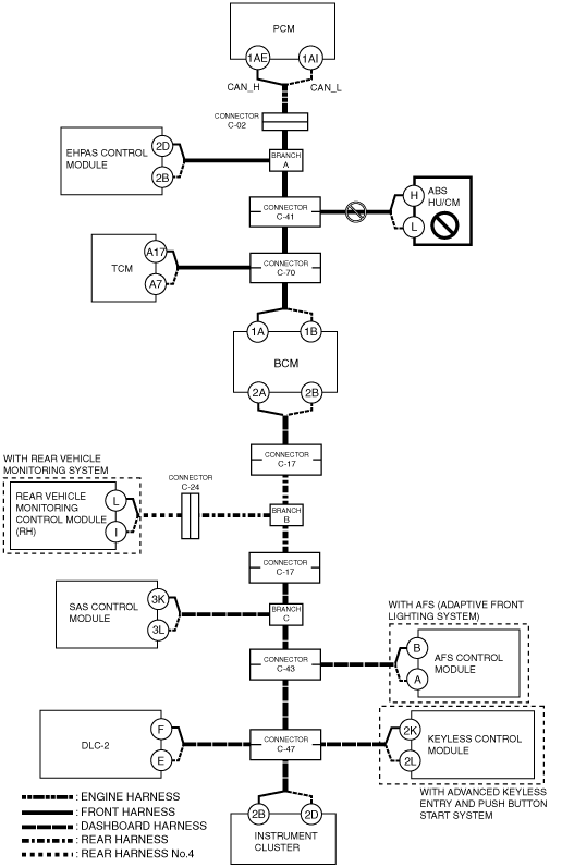
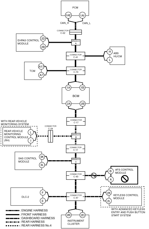
B
Possible cause
System wiring diagram
am3zzw00010503
|
Inspection item
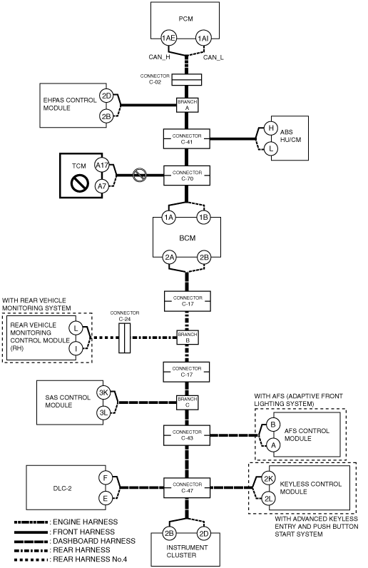
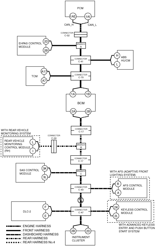
C
Possible cause
System wiring diagram
am3zzw00010504
|
Inspection item
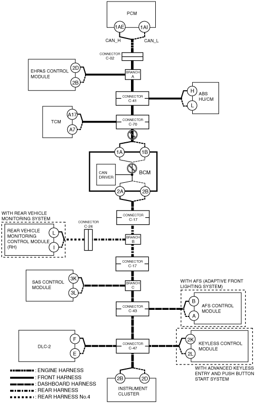
D
Possible cause
System wiring diagram
am3zzw00010505
|
Inspection item
E
Possible cause
System wiring diagram
am3zzw00010506
|
Inspection item
F
Possible cause
System wiring diagram
am3zzw00010507
|
Inspection item
G
Possible cause
System wiring diagram
am3zzw00010508
|
Inspection item
H
Possible cause
System wiring diagram
am3zzw00010509
|
Inspection item
I
Possible cause
System wiring diagram
am3zzw00010510
|
Inspection item
J
Possible cause
System wiring diagram
am3zzw00010511
|
Inspection item
K
Possible cause
System wiring diagram
am3zzw00010512
|
Inspection item
L
Possible cause
System wiring diagram
am3zzw00010513
|
Inspection item
M
Possible cause
System wiring diagram
am3zzw00010514
|
Inspection item
N
Possible cause
System wiring diagram
am3zzw00010515
|
Inspection item
O
Possible cause
System wiring diagram
am3zzw00010516
|
Inspection item
P
Possible cause
System wiring diagram
am3zzw00010517
|
Inspection item
Q
Possible cause
System wiring diagram
am3zzw00010518
|
Inspection item