 |
am3zzw00010525
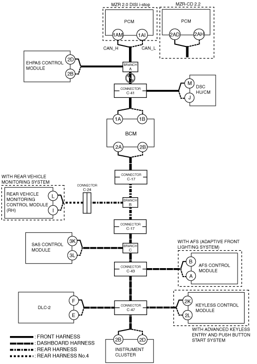
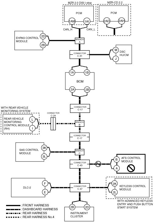
DETERMINING OPEN CIRCUIT LOCATION (HS-CAN) [MULTIPLEX COMMUNICATION SYSTEM (R.H.D. (MZR-CD 2.2, MZR 2.0 DISI i-stop))]
id0902n0837900
1. Verify the CAN system-related module DTCs and the failed module on the M-MDS screen.
2. Apply the communication error DTC and the failed module to DTC output pattern and malfunctioning part, and select the possible cause for the diagnostic result and the reference for the inspection item.
3. Inspect the possible cause and inspection item of the applicable malfunctioning part.
4. After repairing, return to CONTROLLER AREA NETWORK (CAN) MALFUNCTION DIAGNOSIS FLOW [MULTIPLEX COMMUNICATION SYSTEM (R.H.D. (MZR-CD 2.2, MZR 2.0 DISI i-stop))] and verify that the repairs have been completed.
DTC output pattern and malfunctioning part
|
M-MDS display |
DTC output pattern and malfunctioning part |
|||||||||||||||
|---|---|---|---|---|---|---|---|---|---|---|---|---|---|---|---|---|
|
DTC output module |
DTC |
|||||||||||||||
|
PCM
(PCM [MZR 2.0 DISI i-stop])
|
U0121:00
|
|
|
|
×
|
|
|
|
|
|
|
|
|
|
|
|
|
U0131:00
|
|
×
|
|
|
|
|
|
|
|
|
|
|
|
|
|
|
|
U0140:00
|
|
|
|
|
|
×
|
|
|
|
|
|
|
|
|
|
|
|
U0155:00
|
|
|
|
|
|
|
|
|
|
|
|
|
|
|
×
|
|
|
U0214:00
|
|
|
|
|
|
|
|
|
|
|
|
|
|
×
|
|
|
|
PCM
(PCM [MZR-CD 2.2])
|
U0121:00
|
|
|
|
×
|
|
|
|
|
|
|
|
|
|
|
|
|
U0155:00
|
|
|
|
|
|
|
|
|
|
|
|
|
|
|
×
|
|
|
EPS
(EHPAS control module)
|
U0100
|
×
|
|
|
|
|
|
|
|
|
|
|
|
|
|
|
|
U0140
|
|
|
|
|
|
×
|
|
|
|
|
|
|
|
|
|
|
|
U0155
|
|
|
|
|
|
|
|
|
|
|
|
|
|
|
×
|
|
|
ABS
(DSC HU/CM)
|
U0100:00
|
×
|
|
×
|
|
|
|
|
|
|
|
|
|
|
|
|
|
U0140:00
|
|
|
|
|
|
×
|
|
|
|
|
|
|
|
|
|
|
|
U0155:00
|
|
|
|
|
|
|
|
|
|
|
|
|
|
|
×
|
|
|
BCM/GEM
(BCM)
|
U0100:00
|
×
|
|
×
|
|
×
|
|
|
|
|
|
|
|
|
|
|
|
U0121:00
|
|
|
|
×
|
×
|
|
|
|
|
|
|
|
|
|
|
|
|
U0151:00
|
|
|
|
|
|
|
|
|
|
×
|
|
|
|
|
|
|
|
U0214:00
|
|
|
|
|
|
|
|
|
|
|
|
|
|
×
|
|
|
|
RVM*1
(Rear vehicle monitoring control module (RH))
|
U0100:00
|
×
|
|
×
|
|
×
|
|
×
|
|
|
|
|
|
|
|
|
|
U0121:00
|
|
|
|
×
|
×
|
|
×
|
|
|
|
|
|
|
|
|
|
|
U0140:00
|
|
|
|
|
|
×
|
×
|
|
|
|
|
|
|
|
|
|
|
U0155:00
|
|
|
|
|
|
|
|
|
|
|
|
|
|
|
×
|
|
|
RCM
(SAS control module)
|
U0155
|
|
|
|
|
|
|
|
|
|
|
|
|
|
|
×
|
|
AFS*2
(AFS control module)
|
U0100:00
|
×
|
|
×
|
|
×
|
|
×
|
|
×
|
|
×
|
|
|
|
|
|
U0140:00
|
|
|
|
|
|
×
|
×
|
|
×
|
|
×
|
|
|
|
|
|
|
RKE*3
(Keyless control module)
|
U0100:00
|
×
|
|
×
|
|
×
|
|
×
|
|
×
|
|
×
|
|
×
|
|
|
|
U0121:00
|
|
|
|
×
|
×
|
|
×
|
|
×
|
|
×
|
|
×
|
|
|
|
|
IC
(Instrument cluster)
|
U0100:00
|
×
|
|
×
|
|
×
|
|
×
|
|
×
|
|
×
|
|
×
|
|
|
|
U0121:00
|
|
|
|
×
|
×
|
|
×
|
|
×
|
|
×
|
|
×
|
|
|
|
|
U0131:00
|
|
×
|
×
|
|
×
|
|
×
|
|
×
|
|
×
|
|
×
|
|
|
|
|
U0140:00
|
|
|
|
|
|
×
|
×
|
|
×
|
|
×
|
|
×
|
|
|
|
|
U0151:00
|
|
|
|
|
|
|
|
|
|
×
|
×
|
|
×
|
|
|
|
|
U0182:00
|
|
|
|
|
|
|
|
|
|
|
|
×
|
×
|
|
|
|
|
U0214:00
|
|
|
|
|
|
|
|
|
|
|
|
|
|
×
|
|
|
|
U0232:00
|
|
|
|
|
|
|
|
×
|
×
|
|
×
|
|
×
|
|
|
|
|
M-MDS display module
|
[Fail] display pattern
|
|||||||||||||||
|
PCM
|
×
|
|
×
|
|
×
|
|
×
|
|
×
|
|
×
|
|
×
|
|
|
|
|
EPS
|
|
×
|
×
|
|
×
|
|
×
|
|
×
|
|
×
|
|
×
|
|
|
|
|
ABS
|
|
|
|
×
|
×
|
|
×
|
|
×
|
|
×
|
|
×
|
|
|
|
|
BCM/GEM
|
|
|
|
|
|
×
|
×
|
|
×
|
|
×
|
|
×
|
|
|
|
|
RVM*1
|
|
|
|
|
|
|
|
×
|
×
|
|
×
|
|
×
|
|
|
|
|
RCM
|
|
|
|
|
|
|
|
|
|
×
|
×
|
|
×
|
|
|
|
|
AFS*2
|
|
|
|
|
|
|
|
|
|
|
|
×
|
×
|
|
|
|
|
RKE*3
|
|
|
|
|
|
|
|
|
|
|
|
|
|
×
|
|
|
|
IC
|
|
|
|
|
|
|
|
|
|
|
|
|
|
|
×
|
|
|
Diagnostic result
|
||||||||||||||||
|
Possible cause and inspection item
|
A
|
B
|
C
|
D
|
E
|
F
|
G
|
H
|
I
|
J
|
K
|
L
|
M
|
N
|
O
|
|
|
Reference page
|
||||||||||||||||
A
Possible cause
System wiring diagram
am3zzw00010525
|
Inspection item
B
Possible cause
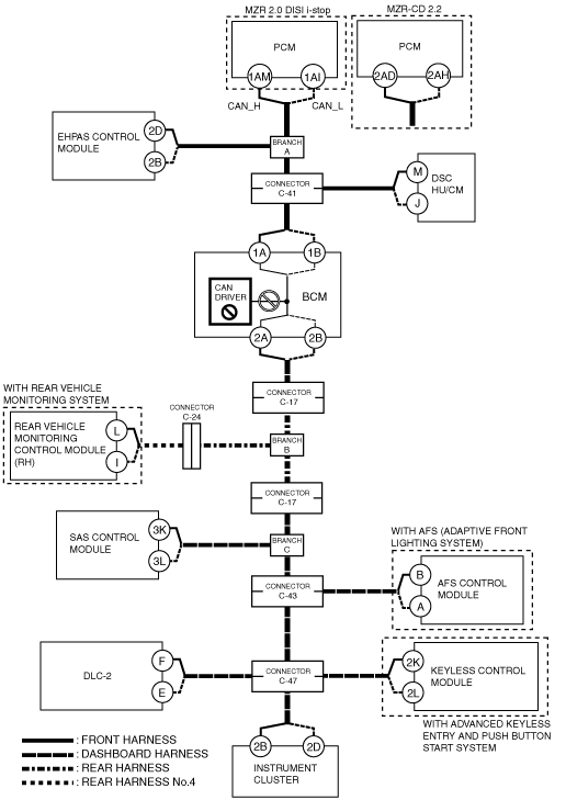
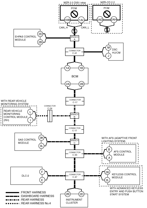
System wiring diagram
am3zzw00010526
|
Inspection item
C
Possible cause
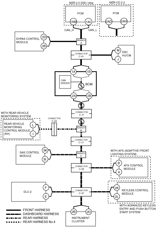
System wiring diagram
am3zzw00010527
|
Inspection item
D
Possible cause
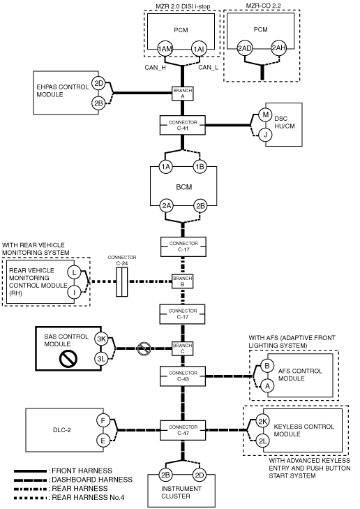
System wiring diagram
am3zzw00010528
|
Inspection item
E
Possible cause
System wiring diagram
am3zzw00010529
|
Inspection item
F
Possible cause
System wiring diagram
am3zzw00010530
|
Inspection item
G
Possible cause
System wiring diagram
am3zzw00010531
|
Inspection item
H
Possible cause
System wiring diagram
am3zzw00010532
|
Inspection item
I
Possible cause
System wiring diagram
am3zzw00010533
|
Inspection item
J
Possible cause
System wiring diagram
am3zzw00010534
|
Inspection item
K
Possible cause
System wiring diagram
am3zzw00010535
|
Inspection item
L
Possible cause
System wiring diagram
am3zzw00010536
|
Inspection item
M
Possible cause
System wiring diagram
am3zzw00010537
|
Inspection item
N
Possible cause
System wiring diagram
am3zzw00010538
|
Inspection item
O
Possible cause
System wiring diagram
am3zzw00010539
|
Inspection item