 |
am3uuw00002540
INSTRUMENT CLUSTER INSPECTION
id092200010600
Speedometer
Using a speedometer tester
1. Adjust the tire pressure to the specification.
2. Using a speedometer tester, verify that the tester reading is as indicated in the table below.
3. Verify that the speedometer reading is within the range indicated in the table.
European (L.H.D. U.K.), General (L.H.D. R.H.D.) specs.
|
Speedometer tester indication (km/h) |
Allowable range (km/h) |
|---|---|
|
20
|
20—25
|
|
40
|
41—45
|
|
60
|
61—66
|
|
80
|
82—87
|
|
100
|
103—109
|
|
120
|
123—130
|
|
140
|
144—151
|
Australian specs. (Except MZR 2.3 DISI Turbo)
|
Speedometer tester indication (km/h) |
Allowable range (km/h) |
|---|---|
|
20
|
20—25
|
|
40
|
40—45
|
|
60
|
61—66
|
|
80
|
81—87
|
|
100
|
102—108
|
|
120
|
122—130
|
|
140
|
143—150
|
U.K. specs. (Except MZR 2.3 DISI Turbo)
|
Speedometer tester indication (mph) |
Allowable range (mph) |
|---|---|
|
10
|
10—13
|
|
20
|
20—23
|
|
30
|
30—34
|
|
40
|
41—44
|
|
50
|
51—55
|
|
60
|
61—66
|
|
70
|
72—76
|
|
80
|
82—87
|
European (L.H.D. U.K.) specs. (MZR 2.3 DISI Turbo)
|
Speedometer tester indication (km/h) |
Allowable range (km/h) |
|---|---|
|
20
|
20—26
|
|
40
|
41—46
|
|
60
|
62—67
|
|
80
|
82—88
|
|
100
|
103—110
|
|
120
|
124—131
|
|
140
|
145—153
|
Australian specs. (MZR 2.3 DISI Turbo)
|
Speedometer tester indication (km/h) |
Allowable range (km/h) |
|---|---|
|
20
|
20—25
|
|
40
|
40—46
|
|
60
|
61—66
|
|
80
|
81—87
|
|
100
|
102—108
|
|
120
|
122—129
|
|
140
|
143—150
|
U.K. specs. (MZR 2.3 DISI Turbo)
|
Speedometer tester indication (mph) |
Allowable range (mph) |
|---|---|
|
10
|
10—14
|
|
20
|
20—24
|
|
30
|
31—34
|
|
40
|
41—45
|
|
50
|
51—56
|
|
60
|
62—66
|
|
70
|
72—77
|
|
80
|
82—88
|
General (R.H.D.) specs. (SKYACTIV-G 2.0)
|
Speedometer tester indication (km/h) |
Allowable range (km/h) |
|---|---|
|
20
|
19—24
|
|
40
|
41—45
|
|
60
|
61—65
|
|
80
|
82—86
|
|
100
|
102—108
|
|
120
|
123—128
|
|
140
|
145—149
|
Using the M-MDS
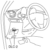
1. Connect the M-MDS (IDS) to the DLC-2.
am3uuw00002540
|
2. After the vehicle is identified, select the following items from the initialization screen of the IDS.
3. Verify that it is displayed according to the table using “SPDMTR”.
|
M-MDS display
|
Instrument cluster display
|
|
60 km/h
|
Speedometer gauge needle moves to approx. 60 km/h
|
|
120 km/h
|
Speedometer gauge needle moves to approx. 120 km/h
|
|
Off
|
Speedometer gauge needle moves to 0 km/h
|
Tachometer
1. Connect the M-MDS (IDS) to the DLC-2.
am3uuw00002540
|
2. After the vehicle is identified, select the following items from the initialization screen of the IDS.
3. Verify that it is displayed according to the table using “TACHOMTR”.
|
M-MDS display
|
Instrument cluster display
|
|
3000 RPM
|
Tachometer gauge needle moves to approx. 3,000 rpm
|
|
6000 RPM
|
Tachometer gauge needle moves to approx. 6,000 rpm
|
|
Off
|
Tachometer gauge needle moves to 0 rpm
|
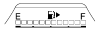
Fuel gauge
1. Connect the M-MDS (IDS) to the DLC-2.
am3uuw00002540
|
2. After the vehicle is identified, select the following items from the initialization screen of the IDS.
3. Verify that it is displayed according to the table using “LCD_SEG”.
Type A
am3zzw00007014
|
Type B
am3uuw00004574
|
Boost gauge
1. Connect the M-MDS (IDS) to the DLC-2.
am3uuw00002540
|
2. After the vehicle is identified, select the following items from the initialization screen of the IDS.
3. Verify that it is displayed according to the table using “LCD_SEG”.
Type A
am3uuw00005741
|
Type B
aaxjjw00006093
|