 |
am3zzn00004303
ON-BOARD DIAGNOSTIC SYSTEM [LASER SENSOR]
id0402c4181300
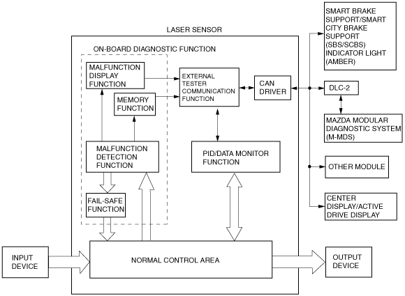
OUTLINE
Block diagram
am3zzn00004303
|
FUNCTION
Malfunction detection function
Memory function
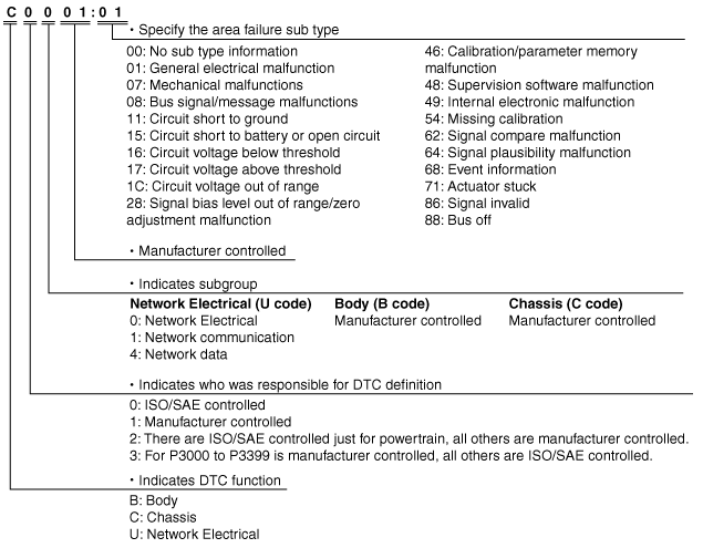
DTC 7-digit code definition
am5ezn00001087
|
Fail-safe function
DTC table
|
DTC No. |
Smart City Brake Support (SCBS) indicator light (amber) |
Fail-safe function |
Malfunction location |
Drive cycle |
Self test type*1 |
Memory function |
|---|---|---|---|---|---|---|
|
U0001:00
|
Illuminated
|
Smart City Brake Support (SCBS) control disabled
|
CAN line
|
-
|
C
|
×
|
|
U0100:00
|
||||||
|
U0121:00
|
||||||
|
U0131:00
|
||||||
|
U0155:00
|
||||||
|
U0401:68
|
Illuminated
|
Smart City Brake Support (SCBS) control disabled
|
Abnormal message from PCM
|
-
|
C
|
×
|
|
U0415:68
|
Illuminated
|
Smart City Brake Support (SCBS) control disabled
|
Abnormal message from DSC HU/CM
|
-
|
C
|
×
|
|
U0420:68
|
Illuminated
|
Smart City Brake Support (SCBS) control disabled
|
Abnormal message from EPS CM
|
-
|
C
|
×
|
|
U0423:68
|
Illuminated
|
Smart City Brake Support (SCBS) control disabled
|
Abnormal message from instrument cluster
|
-
|
C
|
×
|
|
U1A14:49
|
Illuminated
|
Smart City Brake Support (SCBS) control disabled
|
Laser sensor
|
-
|
C
|
×
|
|
U2300:55
|
Illuminated
|
Smart City Brake Support (SCBS) control disabled
|
Configuration data not recorded or data error
|
-
|
C
|
×
|
|
U2300:56
|
Smart City Brake Support (SCBS) control disabled
|
-
|
C
|
×
|
||
|
U3000:00
|
Illuminated
|
Smart City Brake Support (SCBS) control disabled
|
Laser sensor (internal malfunction)
|
-
|
C
|
×
|
|
U3000:64
|
Smart City Brake Support (SCBS) control disabled
|
-
|
C
|
×
|
||
|
U3000:66
|
Illuminated
|
Smart City Brake Support (SCBS) control disabled
|
Laser sensor
|
-
|
C
|
×
|
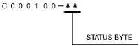
Status byte for DTC
am5ezn00002077
|
Snapshot data
|
Snapshot data item |
Unit |
Definition |
Corresponding data monitor items |
|---|---|---|---|
|
DSC_R_BRK
|
OK/Error
|
DSC response against brake request from SCBS module
|
—
|
|
DSC_R_BRK_C
|
OK/Error
|
DSC response against brake assist threshold change from SCBS module
|
—
|
|
DSC_R_NOREQ
|
OK/Error
|
DSC response while no request from SCBS module
|
—
|
|
DSC_R_PRECH
|
OK/Error
|
DSC response against pre-charge request from SCBS module
|
—
|
|
DSC_SYSTEM
|
OK/Error
|
DSC system condition
|
—
|
|
ECU_IN_TEMP
|
°C
|
ECU internal temperature
|
—
|
|
PCM_R_NOREQ
|
OK/Error
|
PCM response while no request from SCBS module
|
—
|
|
PCM_R_REQ
|
OK/Error
|
PCM response against request from SCBS module
|
—
|
|
PCM_SYSTEM
|
OK/Error
|
PCM system condition
|
—
|
|
TOTAL_DIST
|
km, ft, mi
|
Total distance
|
—
|
|
TOTAL_TIME
|
hh:mm:ss
|
Total time
|
—
|
|
VPWR
|
V
|
Power supply
|
—
|
|
VSPD
|
KPH, MPH
|
Vehicle speed
|
—
|
PID/data monitor function
PID/data monitor table
|
Mazda Modular Diagnostic System (M-MDS) display |
Data contents |
Unit/Operation (Mazda Modular Diagnostic System (M-MDS) display) |
|---|---|---|
|
DIST_BMP_TGT
|
Distance from bumper to target that sensor has detected
|
m
|
|
VPWR_IG1
|
Module supply voltage (IG1)
|
V
|
|
VSPD
|
Vehicle speed
|
KPH, MPH
|
External tester communication function
Connections/communication contents
|
External tester |
||
|---|---|---|
|
Mazda Modular Diagnostic System (M-MDS) |
||
|
Connection |
Communication method |
|
|
On-board diagnostic (malfunction detection) function
|
Input/output: CAN_H (HS), CAN_L (HS) terminals
|
Serial communication
|
|
PID/data monitor function
|
Input/output: CAN_H (HS), CAN_L (HS) terminals
|
Serial communication
|
|
Diagnostic function name |
Signal received |
Signal sent |
|---|---|---|
|
Malfunction detection function
|
DTC verification signal
|
DTC
|
|
PID/data monitor function
|
Command signal to read selected monitor item
|
Monitored data for requested monitor item
|