FULL-AUTO AIR CONDITIONER SYSTEM [FULL-AUTO AIR CONDITIONER]
id0740a1004000
Outline
• The climate control unit performs the following controls based on the signals from each switch/dial and the sensor.
|
Basic control
|
Control description
|
Correction control
|
|
Airflow temperature control
|
Airflow temperature automatic control
|
• MAX HOT and MAX COLD correction
• Engine coolant temperature correction
|
|
Airflow volume control
|
Airflow volume automatic control
|
• Engine coolant temperature correction (warm-up correction)
• Mild start correction
• MAX HOT and MAX COLD correction
• Defroster correction
• Start-up window fogging prevention correction
• Starting compensation correction
• Start-up burnt-out prevention function
|
|
Airflow volume manual control
|
• Defroster correction
• Starting burnt-out prevention function
|
|
Airflow mode control
|
Airflow mode automatic control
|
• Engine coolant temperature correction (warm-up correction)
|
|
Airflow mode manual control
|
—
|
|
Air intake control
|
Air intake automatic control
|
• Defroster correction
• Ambient temperature correction
|
|
Air intake manual control
|
• Defroster correction
|
|
A/C compressor control
|
A/C compressor automatic control
|
• Defroster correction
|
|
A/C compressor manual control
|
|
A/C cut-off control
|
|
Supplementary function
|
|
Fail-safe function
|
|
Air conditioner i-stop control
|
|
Sensor signal delay function
|
On-board diagnostic function (See ON-BOARD DIAGNOSTIC.) |
Function
Airflow temperature control
-
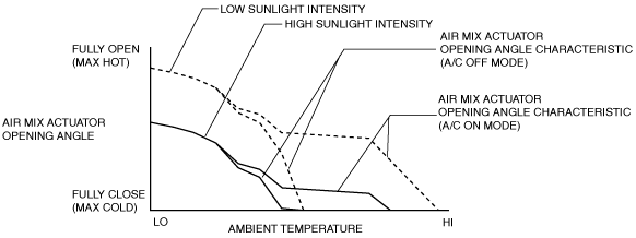
• The air mix actuator is driven and the air mix door position is changed according to the set temperature and the vehicle environment.
• The climate control unit calculates the air mix actuator opening angle characteristic based on the set temperature, solar radiation amount, and airflow mode.
• The air mix actuator opening angle characteristic is set lower as the sunlight intensity increases.
• The airflow temperature is automatically controlled continuously.
• The airflow temperature control performs the following corrections:
-
― MAX HOT and MAX COLD correction
― Engine coolant temperature correction
-
MAX HOT and MAX COLD correction
-
• Under the MAX HOT and MAX COLD correction, the air mix actuator opening angle is fixed at fully open when the temperature is set to 29.0/84, and fixed at fully closed when the temperature is set to 15/60. (European (L.H.D. U.K.) specs.).
• Under the MAX HOT and MAX COLD correction, the air mix actuator opening angle is fixed at fully open when the temperature is set to 32.0/90, and fixed at fully closed when the temperature is set to 18/64. (except European (L.H.D. U.K.) specs.).
-
Engine coolant temperature correction
-
• The engine coolant temperature correction prevents cold air from passing through the air vents after the engine is started in winter.
• When the engine coolant temperature is lower than the specified value, the air mix actuator opening angle is corrected to the HOT side.
• The engine coolant temperature correction is not performed when the ambient temperature is 15 °C {59 °F}or more.
Airflow volume control
-
• The airflow volume control changes the operation of the blower motor according to the operations of the airflow volume control dial or temperature control dial and the vehicle environment to change the airflow volume.
• The airflow volume control has automatic and manual controls.
-
• The airflow volume automatic control performs the following correction:
-
― Engine coolant temperature correction (warm-up correction)
― Mild start correction
― MAX HOT and MAX COLD correction
― Start-up window fogging prevention correction
― Starting compensation correction
― Defroster correction
― Start-up burn-out prevention function
-
Airflow Volume Automatic Control
-
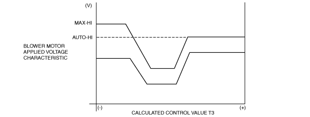
• The climate control unit calculates the blower motor applied voltage characteristic based on the set temperature, ambient temperature, and solar radiation amount.
• The climate control unit compares the blower motor applied voltage characteristic with the target temperature (calculated control value T3) and then determines the blower motor applied voltage (AUTO voltage).
• Calculated control value T3 is the target cabin temperature as set by the climate control unit based on differences between the set temperatures and temperatures input from the sensors.
• Calculated control value T3 is constantly calculated according to the changes in the set temperature and the signals input from the sensors.
-
Airflow Volume Manual Control
-
• The climate control unit changes the blower fan motor applied voltage in seven steps according to the operation of the airflow volume control switch or dial.
|
Airflow volume control dial
|
Blower motor applied voltage
|
|
1st
|
3.2 V
|
|
2nd
|
4.8 V
|
|
3rd
|
6.4 V
|
|
4th
|
7.9 V
|
|
5th
|
10.1 V
|
|
6th
|
11.2 V
|
|
7th
|
12.5 V
|
-
Engine coolant temperature correction (warm-up correction)
-
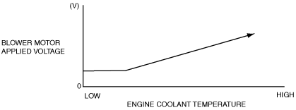
• The engine coolant temperature correction (warm-up correction) prevents high volume of cold air from passing through the air vents after engine start in winter.
• The engine coolant temperature correction (warm-up correction) controls the blower motor applied voltage according to the increase in the engine coolant temperature.
• The engine coolant temperature correction is not performed during defroster correction, or when the cabin temperature is 20 °C {68 °F} or more and the airflow mode is in VENT mode.
-
Mild start correction
-
• The mild start correction prevents a high volume of warm air from coming out of the air vents when the blower motor is started in summer.
• The mild start correction limits the blower motor applied voltage for 3 s after the blower motor is started.
• The mild start correction is not performed when the cabin temperature is 20 °C {68 °F} or less or the airflow is in any mode other than VENT.
-
MAX HOT and MAX COLD correction
-
• The MAX HOT and MAX COLD correction fixes the blower motor applied voltage as indicated in the table when the temperature is set to MAX HOT or MAX COLD.
• The MAX HOT correction is not performed during engine coolant temperature correction.
European (L.H.D. U.K.) specs.
|
Correction name
|
Set temperature
|
Blower motor applied voltage
|
|
MAX HOT correction
|
29.0/84
|
12.1 (V): AUTO-HI
|
|
MAX COLD correction
|
15.0/60
|
14.6 (V): MAX-HI
|
Except European (L.H.D. U.K.) specs.
|
Correction name
|
Set temperature
|
Blower motor applied voltage
|
|
MAX HOT correction
|
32.0/90
|
12.1 (V): AUTO-HI
|
|
MAX COLD correction
|
18.0/64
|
14.6 (V): MAX-HI
|
-
Start-up window fogging prevention correction
-
• The start-up window fogging prevention correction prevents the windows from easily fogging when the following conditions are all met:
-
― Right after engine start
― Heater is operated
― Air is blowing from vents for defrosting
• The start-up window fogging prevention correction fixes the blower motor applied voltage at 0 V for 6 s after the ignition is switched ON.
• The start-up window fogging prevention correction is not performed when the airflow mode is in any mode other than HEAT, DEF/HEAT and defroster.
-
Starting compensation correction
-
• When the blower motor is started-up from the stopped status at the lowest speed (3.2 V), the starting compensation correction fixes the blower motor applied voltage at 4.4 V for 2 s to stabilize blower motor start-up operation.
-
Defroster correction
-
• When the defroster switch is turned on, the defroster correction adds a correction (+2 V) to the blower motor applied voltage to increase airflow volume.
-
Start-up burn-out prevention function
-
• The start-up burn-out prevention function prevents the blower motor from being burnt out because of excess current.
• When the blower motor is started-up from the stopped status with a blower motor applied voltage of 4.4 V or more, the blower motor applied voltage is fixed at 4.4 V for 1 s.
Airflow mode control
-
• The airflow mode control drives the airflow mode actuator according to the mode switch, defroster switch, and the vehicle environment and switches the position of the airflow mode door.
• The airflow mode control has automatic and manual controls.
• The airflow mode automatic control performs the following correction:
-
― Engine coolant temperature correction (warm-up correction)
-
Airflow mode automatic control
-
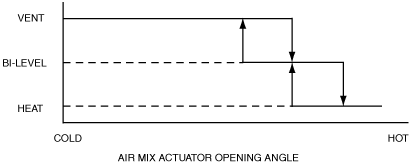
• The climate control unit determines the airflow mode based on the current air mix actuator opening angle and solar radiation amount.
• Determined value used for the airflow mode is changed according to the signal from the solar radiation sensor.
-
Airflow mode manual control
-
• The climate control unit switches the airflow mode based on the MODE switch operation.
|
Airflow mode
|
Operation switch
|
Air vent
|
|
VENT
|
Mode switch
|
CENTER VENT, SIDE VENT
|
|
BI-LEVEL
|
CENTER VENT, SIDE VENT, FRONT HEAT, REAR HEAT
|
|
HEAT
|
FRONT HEAT, REAR HEAT, SIDE DEMISTER (low volume), DEFROSTER (low volume), SIDE VENT (low volume)
|
|
DEF/HEAT
|
FRONT HEAT, REAR HEAT, SIDE DEMISTER, DEFROSTER, SIDE VENT (low volume)
|
|
DEFROSTER
|
DEFROSTER switch
|
SIDE DEMISTER, DEFROSTER, SIDE VENT (low volume)
|
-
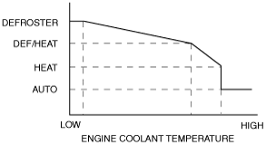
Engine coolant temperature correction (warm-up correction)
-
• The engine coolant temperature correction (warm-up correction) prevents cold air from passing through the lower vents after engine start in winter.
• The engine coolant temperature correction (warm-up correction) switches the airflow mode according to the increase in the engine coolant temperature.
Air intake control
-
• The air intake control drives the air intake actuator and switches the air intake door position according to the operations of the REC, FRESH and defroster switches and the vehicle environment.
• The air intake control has automatic and manual controls.
• The air intake automatic control performs the following correction:
-
― Defroster correction
― Ambient temperature correction
-
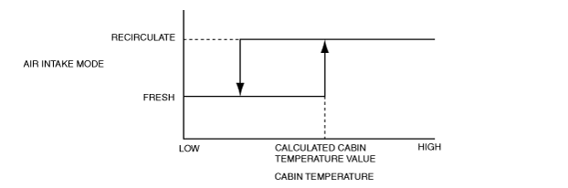
Air intake automatic control
-
• The climate control unit performs the control as follows so that the cabin temperature lowers quickly according to the cooling conditions.
1. Calculates the cabin temperature value based on the ambient temperature and sunlight intensity.
2. Compares the calculated cabin temperature value and current cabin temperature.
3. Determines the air intake mode.
-
Air intake manual control
-
• The climate control unit switches the air intake mode based on the REC/FRESH switch operation.
|
Air intake mode
|
REC switch operation
|
|
FRESH
|
Fixed to FRESH when the FRESH switch is turned on during REC mode
|
|
REC
|
Fixed to REC when the RECIRCULATE switch is turned on during FRESH mode
|
-
REC mode control under severe heat
-
• When the vehicle is driven at a very low speed with the A/C on under a severe heat condition, the climate control unit may change the air intake mode from FRESH to REC automatically.
• Due to this, load to the A/C compressor is reduced.
• When the air intake mode is switched to REC, the indicator on the REC switch illuminates.
-
Defroster correction
-
• The defroster correction improves the effect of defrosting.
• The air intake is fixed at FRESH when the defroster switch is turned on.
• The air intake is fixed at FRESH even if it has been set to REC manually.
-
Ambient temperature correction
-
• When the ambient temperature is 5 °C {41 °F} or less, the air intake is fixed at FRESH to prevent window fogging. (Australian, General (R.H.D.) specs.)
• When the ambient temperature is 15 °C {59 °F} or less, the air intake is fixed at FRESH to prevent window fogging. (except Australian, General (R.H.D.) specs.)
A/C compressor control
-
• The A/C compressor control turns the A/C compressor on/off based on the climate control unit operation and signals from each sensor.
• The A/C compressor control has automatic and manual controls.
• The A/C compressor automatic control performs the following correction:
-
― Defroster correction
-
A/C compressor automatic control
-
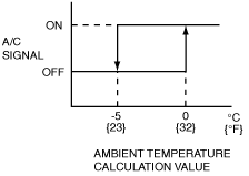
• The climate control unit determines the A/C ON/OFF mode based on the ambient temperature.
• The climate control unit determines the A/C signal on/off according to the air conditioner operation such as A/C ON mode (A/C switch ON) or AUTO mode (AUTO switch ON).
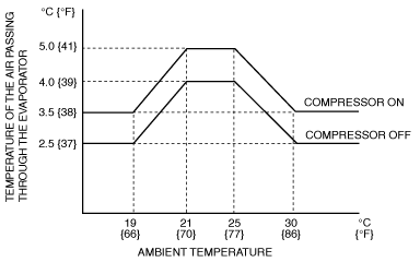
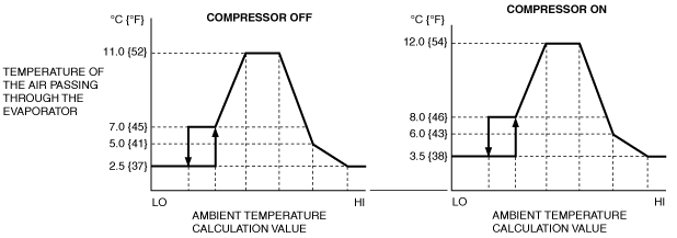
• In A/C ON mode, the A/C signal (magnetic clutch) on/off is determined based on the ambient temperature and the temperature of the air passing through the evaporator.
• In AUTO mode, the A/C signal (magnetic clutch) on/off is determined based on the ambient temperature calculation value and the temperature of the air passing through the evaporator.
• The ambient temperature calculation value is calculated based on the ambient temperature, set temperature, cabin temperature, and sunlight intensity.
• When the ambient temperature is low, the A/C signal (magnetic clutch) OFF temperature is set lower to prevent window fogging.
-
A/C compressor manual control
-
• The climate control unit switches the A/C ON/OFF mode according to the A/C switch operation.
|
A/C mode
|
Operation condition
|
|
A/C ON mode (A/C display)
|
A/C mode (A/C display)
|
Fixed in A/C mode.
|
|
A/C OFF mode (No display)
|
Fixed in A/C OFF mode.
|
|
A/C ON mode (ECO display)
|
ECO mode (ECO display)
|
Fixed in ECO mode.
|
-
Defroster correction
-
• When the defroster switch is turned on, the system is switched to A/C ON mode to improve defogging.
-
A/C cut-off control
-
Sensor Signal Delay Function
-
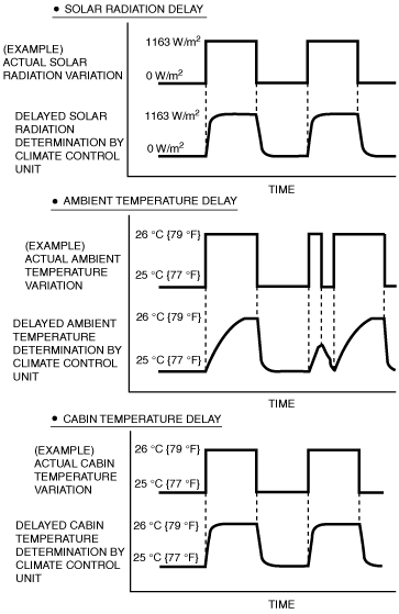
• The amount of solar radiation, and the ambient and cabin temperatures may change due to factors such as direct and intermittent sunlight (traveling through a city or a highway tunnel), or radiant heat from the ground under parked vehicles as well as the opening and closing of doors.
• If control was performed based exactly on these variations, the air conditioning function would be negatively affected and smooth control could not occur.
• In order to prevent this, the climate control unit delays and smooths the input signals for solar radiation, and the ambient and cabin temperature as shown in the following figure, realizing stable control.
• When the engine is restarted after being temporarily stopped, the ambient temperature sensor may detect a temperature higher than the actual ambient temperature.
• To prevent this, if the engine coolant temperature exceeds 55 °C {131 °F}, control of each system is performed based on the ambient temperature data before the engine was stopped, which is stored in the climate control unit.
Air conditioner i-stop control
-
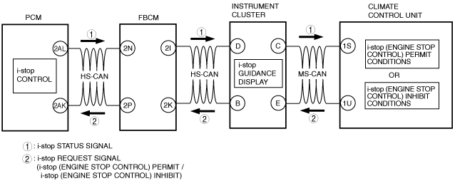
• The climate control unit determines i-stop control according to the operation condition of the air conditioner system and sends i-stop request signals to the PCM.
-
• If i-stop operates (engine stop control), the climate control unit operates the air mix actuator and controls the airflow temperature to decrease the engine coolant temperature or correct the temperature increase of the air passing through the evaporator.
-
Caution
-
• Occupants may hear the sound of the air mix actuator operating because there is no engine sound during the i-stop operation (engine stop control). The operation sound of the air mix actuator may be heard because the airflow temperature control is performed even during the i-stop operation (engine stop control), however, this does not indicate a system malfunction.
Fail-safe
-
• If a malfunction is detected by the malfunction detection function, the fail-safe function performs the following controls to prevent an operation malfunction of the full-auto air conditioner and malfunction of output devices.
Fail-safe function table
|
Part where malfunction is determined
|
Malfunction determined when ignition switched ON
|
Malfunction already exists when ignition switched ON
|
|
Ambient temperature sensor
|
Ambient temperature sensor input value is fixed at the value right before the malfunction.
|
Ambient temperature sensor input value is fixed at 15 °C {59 °F}.
|
|
Cabin compartment temperature sensor
|
Cabin compartment temperature sensor input value is fixed at the value right before the malfunction.
|
Cabin compartment temperature sensor input value is fixed at 25 °C {77 °F}.
|
|
Evaporator temperature sensor
|
A/C output OFF is controlled when the evaporator temperature sensor input value is at 0 °C {32 °F}.
|
←
|
|
Solar radiation sensor
|
The solar radiation sensor input value is fixed at the value directly before the malfunction only when the valve is 1,450 W/m2 or more.
|
Solar radiation sensor value is fixed at 0 W/m2.
|
|
Engine coolant temperature sensor
|
Engine coolant temperature sensor input value is fixed at 85 °C {185 °F}.
|
←
|
|
Air mix actuator
(potentiometer)
|
Air mix actuator drive signal is stopped right when the malfunction is determined.
However, it is fixed at MAX COLD when the manually set temperature is at 15 °C {60 °F} and fixed at MAX HOT when the manually set temperature is at 29 °C {84 °F}.
|
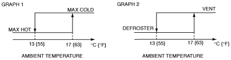
Control based on ambient temperature.
(See Graph 1.)
However, it is fixed at MAX COLD when the manually set temperature is at 15 {60 °F} and fixed at MAX HOT when the manually set temperature is at 29 °C {84 °F}.
|
|
Airflow mode actuator
(potentiometer)
|
Airflow mode actuator drive signal is stopped right when the malfunction is determined.
• However, the operation is change to VENT or DEF when the manual operation is set to VENT or DEF.
|
Control based on ambient temperature.
(See Graph 2.)
• However, the operation is change to VENT or DEF when the manual operation is set to VENT or DEF.
|
|
Air mix actuator
(motor lock)
|
• Air mix actuator drive signal is stopped right when the malfunction is determined.
|
• Twenty seconds after ignition is switched ON, the air mix actuator drive signal is output normally again. Afterwards, motor output is stopped during malfunction determination.
|
|
Airflow mode actuator
(motor lock)
|
• Airflow mode actuator drive signal is stopped right when the malfunction is determined.
|
• Nine seconds after ignition is switched ON, the airflow mode actuator drive signal is output normally again. Afterwards, motor output is stopped during malfunction determination.
|
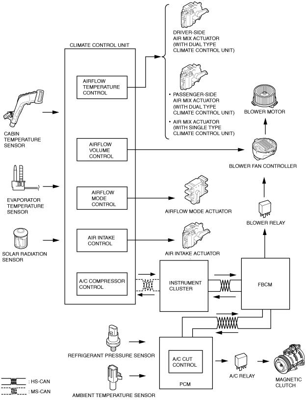
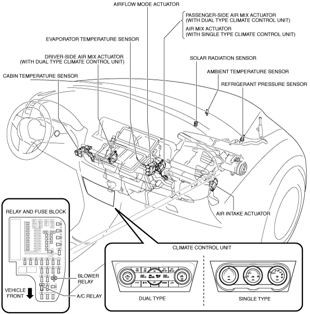
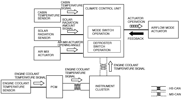
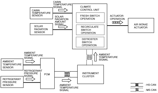
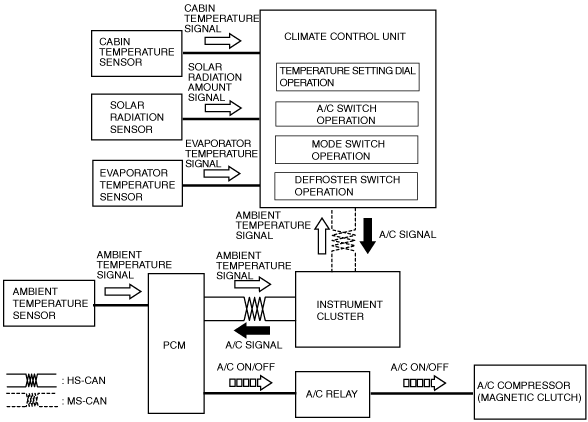
Construction
Block diagram
Structural view
Operation
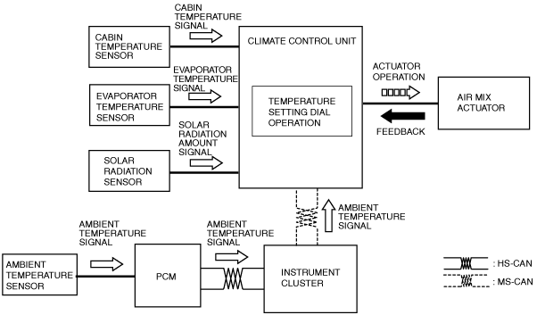
Airflow temperature control
1. The climate control unit determines the airflow temperature based on the temperature control dial operation and signals from each sensor which changes according to the vehicle environment.
2. The climate control unit drives the air mix actuator according to the results of the airflow temperature determination and corrections.
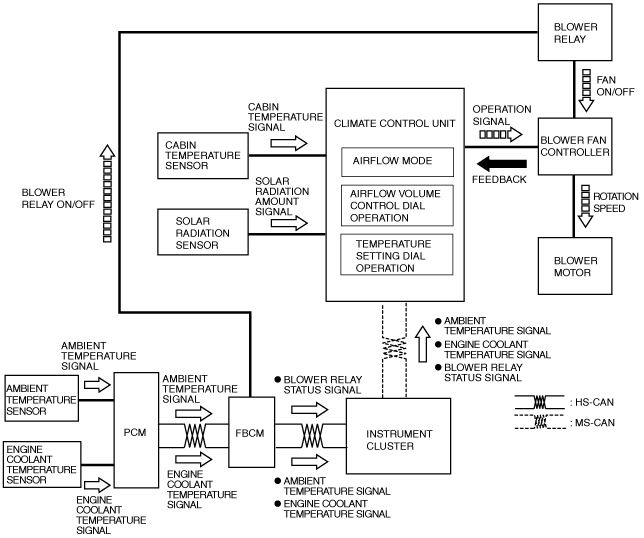
Airflow volume control
1. When the ignition is switched ON (engine off or on), the front body control module (FBCM) turns the blower relay on.
2. When the airflow volume control dial on the climate control unit is turned on, the blower motor rotates.
3. The climate control determines the airflow volume based on the operations of the airflow volume control dial and the temperature setting dial, airflow mode condition, and signals from each sensor.
4. Based on the result of the airflow volume determination and correction, the climate control unit control the blower fan controller and changes the airflow volume (blower motor applied voltage).
5. The rotation speed of the blower motor changes according to the applied voltage from the blower fan controller.
Airflow mode control
1. The climate control unit determines the airflow mode based on the operations of the mode and defroster switches and signals from each sensor which changes according to the vehicle environment.
2. The climate control unit drives the airflow mode actuator according to the results of the airflow mode determination and corrections.
Air intake control
1. The climate control determines the air intake mode based on the operations of the REC, FRESH, defroster switches and signals from each sensor which changes according to the vehicle environment.
2. The climate control unit drives the air intake actuator according to the result of the air intake mode determination and corrections.
A/C compressor control
1. The climate control determines the A/C ON/OFF based on the operations of each switch/dial and signals from each sensor which changes according to the vehicle environment.
2. The climate control unit sends the A/C signal to the PCM according to the result of the A/C ON/OFF determination and corrections.
3. When the PCM turns the A/C relay on based on the A/C signal, the magnetic clutch of the A/C compressor turns on.
Air conditioner i-stop control
-
i-stop request control (i-stop (engine stop control) permit/ i-stop (engine stop control) inhibit)
-
• The climate control unit sends i-stop (engine stop control) permit or i-stop (engine stop control) inhibit request signals to the PCM according to the operation condition of the air conditioner system.
-
i-stop (engine stop control) inhibit request
-
• The climate control unit sends an i-stop (engine stop control) inhibit request signal to the PCM when it detects any of the following conditions:
i-stop (engine stop control) inhibit conditions
|
No.
|
Item
|
Vehicle condition
|
|
1
|
Climate control unit malfunction determined
|
A DTC is detected in relation to the following parts:
• Solar radiation sensor
• Ambient temperature sensor
• Cabin temperature sensor
• Evaporator temperature sensor
• Engine coolant temperature sensor
• Airflow mode actuator
• Air mix actuator
|
|
2
|
CAN line error determined
|
Signal reception error occurs on climate control unit side in relation to the following signals:
• Ambient temperature signal
• Engine coolant temperature signal
• Engine operation status signal (i-stop status signal)
|
|
3
|
Ambient temperature
|
Ambient temperature is -10 °C {14 °F} or below, or 50 °C {122 °F} or more
|
|
4
|
Airflow mode control status
|
During manual defroster control
|
|
5
|
Set temperature, compressor control mode
|
MAX HOT or MAX COLD (A/C or ECO mode)
|
|
6
|
Auto air conditioner target temperature attainment status
|
If any of the following signals do not meet the i-stop (engine stop control) permit conditions (Comfortable cabin temperature control not performed):
• Cabin temperature (cabin target temperature and cabin temperature relation)
• Evaporator temperature
• Heater core temperature
|
-
i-stop (engine stop control) permit request
-
• The climate control unit sends an i-stop (engine stop control) permit request signal to the PCM when it detects any of the following conditions:
i-stop (engine stop control) permit conditions
|
No.
|
Item
|
Vehicle condition
|
|
1
|
Blower motor control status
|
• Blower motor is off
• However, i-stop (engine stop control) inhibit conditions No.1 to 3 must not be in effect.
|
|
2
|
Set temperature, compressor control mode
|
• MAX COLD
• Compressor control: Off
• Blower motor is ON
• However, i-stop (engine stop control) inhibit conditions No.1 to 4 must not be in effect.
|
|
3
|
Auto air conditioner target temperature attainment status
|
• Blower motor is ON
• Compressor control: ON
• The relation between the cabin target temperature and cabin temperature meets the i-stop (engine stop control) permit conditions (comfortable cabin temperature control is performed)
• However, i-stop (engine stop control) inhibit conditions No.1 to 6 must not be in effect.
|
-
A/C control start during i-stop (engine stop control)
-
• When the A/C operation is stopped by the i-stop control, and while i-stop (engine stop control) permit condition No. 3 is met, the climate control unit starts A/C control corresponding to the engine-stop condition if it detects an engine-stop condition based on the i-stop condition signal sent from the PCM.
• If the engine is stopped during A/C control, the A/C compressor magnetic clutch turns off and the A/C indicator light remains in an illuminated condition. When the engine is restarted, the A/C compressor magnetic clutch turns on again.
-
Recovery to normal A/C control
-
• When recovery condition a or b is met while the engine is stopped by the i-stop control, the climate control unit sends an engine restart request signal to the PCM.
• It returns to the normal A/C control when the engine is restarted.
-
Recovery condition a:
-
• i-stop cancel determination condition is met
i-stop (engine stop control) cancel determination conditions
|
Compressor control mode
|
Airflow mode
|
|
VENT
|
BI-LEVEL
|
HEAT, DEF/HEAT, DEFROSTER
|
|
A/C, ECO, OFF
|
If the following conditions are met:
• Evaporator temperature is at i-stop control specification or more
|
If any one of the following conditions are met:
• Evaporator temperature is at i-stop control specification or more
• Heater core temperature is at i-stop control specification or less
|
If the following conditions are met:
• Heater core temperature is at i-stop control specification or less
|
-
Recovery condition b:
-
• Any one of the following i-stop (engine stop control) inhibit conditions is met
-
― No.1 climate control unit malfunction determination
― No.2 CAN transmission error determination
― No.4 mode control status
― No.5 set temperature, compressor control mode