ac5uun00001109
|
ON-BOARD DIAGNOSIS SYSTEM [ADVANCED KEYLESS ENTRY SYSTEM]
id091400111233
Outline
Malfunction detection function
|
DTC No. |
KEY warning light (red) |
Description |
Fail-safe function |
Drive cycle |
Self test type*1 |
Memory function |
|---|---|---|---|---|---|---|
|
B10C6:1F
|
On
|
Keyless antenna (exterior, rear) circuit malfunction
|
×
|
—
|
C, D
|
×
|
|
B10C7:1F
|
On
|
Keyless antenna (interior, rear) circuit malfunction
|
×
|
—
|
C, D
|
×
|
|
B10C9:1F
|
On
|
Keyless antenna (interior, front) circuit malfunction
|
×
|
—
|
C, D
|
×
|
|
B10D1:23
|
On
|
Request switch (LF) circuit malfunction
|
—
|
—
|
C
|
×
|
|
B10D3:23
|
On
|
Request switch (RF) circuit malfunction
|
—
|
—
|
C
|
×
|
|
B11C4:23*2
|
On
|
Request switch (liftgate) circuit malfunction
|
—
|
—
|
C
|
×
|
|
B11FD:1F
|
On
|
Keyless antenna (exterior, LF) circuit malfunction
|
×
|
—
|
C, D
|
×
|
|
B1210:1F
|
On
|
Keyless antenna (exterior, RF) circuit malfunction
|
×
|
—
|
C, D
|
×
|
|
B13C3:04
|
On
|
LF control unit internal malfunction
|
×
|
—
|
C
|
×
|
|
B13C3:09
|
On
|
LF control unit malfunction
|
×
|
—
|
C
|
×
|
|
B13C3:16
|
On
|
LF control unit power supply voltage low input
|
×
|
—
|
C
|
×
|
|
B13C3:29
|
On
|
Communication error between start stop unit and LF control unit
|
×
|
—
|
C
|
×
|
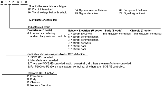
DTC 7-digit code definition
ac5uun00001109
|
Status byte for DTC
ac5wzn00002015
|
Detection condition for the applicable DTC
|
DTC |
System malfunction location |
Detection condition |
|---|---|---|
|
B10C6:1F
|
Keyless antenna (exterior, rear) circuit malfunction
|
Start stop unit detects an open circuit or short to ground in the keyless antenna (exterior, rear) circuit with the ignition switched off.
|
|
B10C7:1F
|
Keyless antenna (interior, rear) circuit malfunction
|
Start stop unit detects an open circuit or short to ground in the keyless antenna (interior, rear) circuit with the ignition switched off.
|
|
B10C9:1F
|
Keyless antenna (interior, front) circuit malfunction
|
Start stop unit detects an open circuit or short to ground in the keyless antenna (interior, front) circuit with the ignition switched off.
|
|
B10D1:23
|
Request switch (LF) circuit malfunction
|
• Start stop unit detected any of the following conditions at a vehicle speed of 5 km/h {3 mph} or more.
|
|
B10D3:23
|
Request switch (RF) circuit malfunction
|
• Start stop unit detected any of the following conditions at a vehicle speed of 5 km/h {3 mph} or more.
|
|
B11C4:23*1
|
Request switch (liftgate) circuit malfunction
|
• Start stop unit detected any of the following conditions at a vehicle speed of 5 km/h {3 mph} or more.
|
|
B11FD:1F
|
Keyless antenna (exterior, LF) circuit malfunction
|
Start stop unit detects an open circuit or short to ground in the keyless antenna (exterior, LF) circuit with the ignition switched off.
|
|
B1210:1F
|
Keyless antenna (exterior, RF) circuit malfunction
|
Start stop unit detects an open circuit or short to ground in the keyless antenna (exterior, RF) circuit with the ignition switched off.
|
|
B13C3:04
|
LF control unit internal malfunction
|
Start stop unit detects the LF control unit internal malfunction.
|
|
B13C3:09
|
LF control unit malfunction
|
• Start stop unit detects that the LF state signal of the LF control unit is low for 5 s or more.
• With the communication between the start stop unit and LF control unit being performed normally, there is no response from the LF control unit even though there is the signal transmission request from the start stop unit to the LF control unit, and the LF state signal becomes low.
|
|
B13C3:16
|
LF control unit power supply voltage low input
|
Start stop unit power supply circuit voltage of 8.5 V or more or less than 16.5 V and LF control unit power supply circuit voltage of 5 V or more or less than 8.5 V are detected for 5 s or more.
|
|
B13C3:29
|
Communication error between start stop unit and LF control unit
|
Start stop unit detects the communication error with the LF control unit 10 times.
|
Data monitor function
|
PID |
Unit/Operation |
Data contents |
Data read/use method |
Module control terminal |
|---|---|---|---|---|
|
LG/T_LK_SW*1
|
Off/On
|
Request switch (liftgate) operation condition
• Off: Request switch (liftgate) is off.
• On: Request switch (liftgate) is on.
|
The request switch (liftgate) input is an input signal to the start stop unit through the LF control unit.
|
2F (LF control unit communication)
|
|
RQ_SW_LF
|
Off/On
|
Request switch (LF) operation condition
• Off: Request switch (LF) is off.
• On: Request switch (LF) is on.
|
The signal is input to the start stop unit through the LF control unit of the request switch (LF).
|
2F (LF control unit communication)
|
|
RQ_SW_RF
|
Off/On
|
Request switch (RF) operation condition
• Off: Request switch (RF) is off.
• On: Request switch (RF) is on.
|
The signal is input to the start stop unit through the LF control unit of the request switch (RF).
|
2F (LF control unit communication)
|
Active Command Modes Function
|
Simulation item |
Unit/Operation |
Data contents |
Data read/use method |
Output part name |
|---|---|---|---|---|
|
BZR_OUT
|
Off/On
|
• Off: Keyless beeper does not sound.
• On: Keyless beeper sounds.
|
• When the simulation item BZR_OUT is turned on, a force override signal is sent to the LF control unit from the start stop unit, and the LF control unit drives (sounds) the keyless beeper.
• With adoption of a separate excitation buzzer to the keyless beeper, buzzer does not sound normally even if the voltage is applied to the buzzer unit because there is no oscillation circuit. The integrity of the keyless beeper is determined using the simulation item BZR_OUT.
• If the keyless buzzer does not sound even though the simulation function BZR_OUT is on, perform diagnosis using the following procedure.
|
Keyless beeper
|