 |
am3zzw00013877
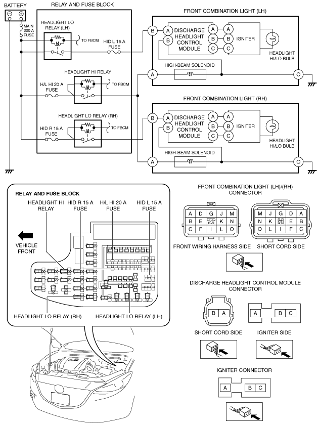
DISCHARGE HEADLIGHT SYSTEM INSPECTION
id091800805400
System Wiring Diagram
am3zzw00013877
|
Diagnostic Procedure
|
Step |
Inspection |
Action |
|
|---|---|---|---|
|
1
|
VERIFY FRONT BODY CONTROL MODULE (FBCM) DTCs
• Perform the DTC inspection for the front body control module (FBCM) using the M-MDS.
• Is a DTC displayed?
|
Yes
|
Repair the malfunctioning location according to the applicable DTC troubleshooting.
|
|
No
|
Go to the next step.
|
||
|
2
|
INSPECT RELAY
• Disconnect the negative battery cable.
• Remove the following relays:
• Inspect the relays.
(See RELAY INSPECTION.)
• Are the relays normal?
|
Yes
|
Install the relays, then go to the next step.
|
|
No
|
Replace the malfunctioning relay.
|
||
|
3
|
INSPECT LIGHT SWITCH
• Inspect the light switch.
(See LIGHT SWITCH INSPECTION.)
• Is the light switch normal?
|
Yes
|
Install the light switch, then go to the next step.
|
|
No
|
Replace the light switch.
|
||
|
4
|
INSPECT FRONT COMBINATION LIGHT CONNECTOR
• Disconnect the front combination light connector.
• Inspect the connector engagement and connection condition and inspect the terminals for damage, deformation, corrosion, or disconnection.
• Is the connector normal?
|
Yes
|
Go to the next step.
|
|
No
|
Repair or replace the connector.
|
||
|
5
|
INSPECT FRONT COMBINATION LIGHT GROUND CIRCUIT FOR OPEN CIRCUIT
• Verify that the front combination light connector is disconnected.
• Inspect for continuity between front combination light terminal O (front wiring harness side) and body ground.
• Is there continuity?
|
Yes
|
Go to the next step.
|
|
No
|
Refer to the wiring diagram and verify if there is a common connector between front combination light terminal O and body ground.
If there is a common connector:
• Inspect the common connector and terminals for corrosion, damage, or disconnection and the common wiring harnesses for open circuit to determine the malfunctioning location.
• Repair or replace the malfunctioning location.
If there is no common connector:
• Repair or replace the wiring harness which has an open circuit.
|
||
|
6
|
INSPECT HEADLIGHT LO POWER SUPPLY CIRCUIT
• Verify that the front combination light connector is disconnected.
• Connect the negative battery cable.
• Operate the light switch to the HEAD position.
• Measure the voltage at front combination light terminal B (front wiring harness side).
• Is the voltage B+?
|
Yes
|
Operate the light switch to the OFF position, then go to the next step.
|
|
No
|
Inspect the HID L 15 A fuse and HID R 15 A fuse.
• If a fuse is blown:
• If a fuse is damaged:
• If both fuses are normal:
|
||
|
7
|
INSPECT HEADLIGHT HI POWER SUPPLY CIRCUIT
• Verify that the front combination light connector is disconnected.
• Operate the light switch to the HEAD and HI position.
• Measure the voltage at front combination light terminal A (front wiring harness side).
• Is the voltage B+?
|
Yes
|
Operate the light switch to the OFF position, then go to the next step.
|
|
No
|
Inspect the H/L HI 20 A fuse.
• If the fuse is blown:
• If the fuse is damaged:
• If the fuse is normal:
|
||
|
8
|
INSPECT DISCHARGE HEADLIGHT CONTROL MODULE CONNECTOR
• Disconnect the negative battery cable.
• Disconnect the discharge headlight control module connector.
• Inspect the connector engagement and connection condition and inspect the terminals for damage, deformation, corrosion, or disconnection.
• Is the connector normal?
|
Yes
|
Go to the next step.
|
|
No
|
Repair or replace the connector.
|
||
|
9
|
INSPECT FRONT COMBINATION LIGHT INTERNAL CIRCUIT FOR OPEN CIRCUIT
• Verify that the following connectors are disconnected.
• Inspect for continuity in the wiring harness between the following terminals:
• Is there continuity?
|
Yes
|
Go to the next step.
|
|
No
|
Replace the front combination light.
|
||
|
10
|
VERIFY IF MALFUNCTION CAUSE IS HEADLIGHT HI/LO BULB
• Install a normal headlight HI/LO bulb.
• Reconnect all the disconnected connectors.
• Connect the negative battery cable.
• Operate the light switch to the HEAD position.
• Does the headlight LO turn on?
|
Yes
|
Replace the headlight HI/LO bulb.
|
|
No
|
Operate the light switch to the OFF position, then go to the next step.
|
||
|
11
|
VERIFY IF MALFUNCTION CAUSE IS DISCHARGE HEADLIGHT CONTROL MODULE OR IGNITER
• Disconnect the negative battery cable.
• Install a normal igniter.
(See IGNITER REMOVAL/INSTALLATION.)
• Connect the negative battery cable.
• Operate the light switch to the HEAD position.
• Does the headlight LO turn on?
|
Yes
|
Replace the igniter.
(See IGNITER REMOVAL/INSTALLATION.)
|
|
No
|
Replace the discharge headlight control module.
|
||